Temperature monitoring device and method for motor of conveying unit and circulating type conveying system

The technology of a conveying system and a conveying unit is applied in the field of a temperature monitoring device for a motor of a conveying unit and a circulating conveying system, which can solve the problems of a large number of motors, increase costs, and limited promotion, and achieve saving of labor and material costs, The effect of improving production efficiency and avoiding measurement errors

Pending Publication Date: 2020-12-22
BMW BRILLIANCE AUTOMOTIVE
View PDF0 Cites 0 Cited by
  • Summary
  • Abstract
  • Description
  • Claims
  • Application Information

AI Technical Summary

Problems solved by technology

[0004] There are many defects in such a temperature measurement method: First, the entire conveying system involves a large number of motors
Installing a temperature sensor for each motor will significantly increase the cost, thus its large-scale promotion is limited; second, the working power supply of the temperature sensor installed on the motor is usually a battery. When the battery power is insufficient or the battery life expires, it cannot Avoid the need to replace batteries or sensors, and this causes additional maintenance costs and undesirable downtime; third, each temperature sensor attached to the motor needs to be numbered in advance, and it may also be necessary to replace the motor or temperature sensor. Rewrite the number information, which will cause a huge workload when the number of replacements is large, and it is not easy to maintain in real time

Method used


Image

  • Temperature monitoring device and method for motor of conveying unit and circulating type conveying system
  • Temperature monitoring device and method for motor of conveying unit and circulating type conveying system
  • Temperature monitoring device and method for motor of conveying unit and circulating type conveying system

Examples


Embodiment Construction

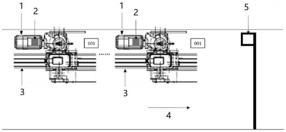
[0059] figure 1 Shown is a prior art temperature measurement of a motor 1 in a vehicle manufacturing line, ie in a conveying system. The motor 1 is used to drive a conveyor unit (not shown in detail) on a support beam 3 of the conveyor system and / or to adjust the height of the conveyor unit. In the illustration shown, a plurality of conveyor units 001 to 101 on a support beam 3 are each assigned an electric motor 1 for moving the respective conveyor unit in the advancing direction 4 . A shaded temperature sensor 2 is attached to each motor 1 . When the motor passes a fixed position where the reading device 5 is installed, the reading device 5 non-contactly reads the temperature of the motor measured by the temperature sensor 1 . In temperature measurement according to the prior art, it is unavoidable to install temperature sensors 2 for a large number of motors. Since the temperature sensor 2 needs to be powered separately and uniquely numbered, additional costs are incurre...


PUM


Abstract

The invention relates to a temperature monitoring device for a motor of a conveying unit of a circulating type conveying system; the motor is arranged on the conveying unit and by means of which the motor can be cyclically operated along a support beam of the conveying system and / or the height of which the motor can be adjusted, the temperature monitoring device comprises a data acquisition module, a data transmission module and a data processing module; the data acquisition module is arranged on the upper side of the supporting beam and comprises an image recognition device and an infrared measurement device which are used for shooting images of the passing conveying unit and / or the motor thereof, respectively, identifying the number associated with the motor in the images, and infrared-measuring the temperature of the passing motor therebelow; the data transmission module performs data transmission in a manner of correlating the identified serial number with the measured temperature;the data processing module processes transmitted data and outputs a temperature monitoring signal. In addition, the invention also relates to a temperature monitoring method for the motor of the conveying unit of the circulating type conveying system and the circulating type conveying system.

Description

technical field [0001] The invention relates to a temperature monitoring device for a motor of a conveying unit of a circulating conveying system, a temperature monitoring method for a motor of a conveying unit of a circulating conveying system, and a circulating conveying system. Background technique [0002] In vehicle manufacturing, a circular conveying system is usually used, whose main function is to lift and convey the vehicle body with the conveying unit for further processing the vehicle body and assembling parts thereto. One or more electric motors are installed for moving the conveyor unit along the support beams of the conveyor system and, if necessary, for adjusting the height of the hoisted bodywork etc. Here, the one or more motors move together with the conveyor unit along the support beam of the conveyor system, and are therefore referred to as mobile motors. In order to ensure the safe and stable operation of these motors, their temperature needs to be moni...

Claims


Application Information

Patent Timeline
IPC IPC(8): G05B19/048
CPCG05B19/048
Inventor 陈卫华毛瑞杰马骥杨洁
Owner BMW BRILLIANCE AUTOMOTIVE
Why Eureka
Try Eureka