
Indoor electromagnetic environment prediction method based on combination of MoM and UTD

An electromagnetic environment and prediction method technology, applied in the field of computational electromagnetics, can solve the problems of inability to solve the model edge diffraction ray problem, inability to accurately calculate the antenna radiation field, and increase in computing resource occupation, so as to reduce labor costs and material costs, The effect of improving the accuracy and speeding up the calculation speed

Pending Publication Date: 2019-10-11
XIDIAN UNIV
View PDF3 Cites 1 Cited by
  • Summary
  • Abstract
  • Description
  • Claims
  • Application Information

AI Technical Summary

Problems solved by technology

MoM was first proposed by G.Petrov, and then introduced by R.F. Harrington and explained its application analysis in the field of electromagnetic calculation. The method of moments has been widely used due to its high accuracy, but when the frequency increases , the calculation resource occupation of this method increases sharply, so this method is not suitable for computing indoor-scale electrically large-scale problems; In terms of design, and the calculation of electromagnetic waves in complex environments, such as urban communities, etc., there are good applications in electromagnetic propagation calculations, but the UTD method cannot accurately calculate the radiation field of the antenna, and there will be infinite results in the caustic zone
In the calculation of indoor electromagnetic environment problems, the bouncing ray method SBR is also used in the high frequency method, but this method cannot solve the problem of diffraction rays existing at the edge of the model, and the lack of rays will lead to inaccurate simulation results

Method used


Image

  • Indoor electromagnetic environment prediction method based on combination of MoM and UTD
  • Indoor electromagnetic environment prediction method based on combination of MoM and UTD
  • Indoor electromagnetic environment prediction method based on combination of MoM and UTD

Examples


Embodiment Construction

[0027] The embodiments and effects of the present invention will be described in further detail below in conjunction with the accompanying drawings.

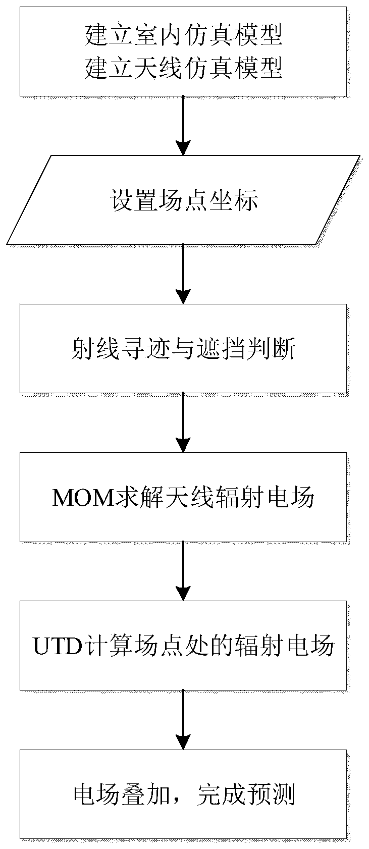
[0028] refer to figure 1 , the implementation steps of this example are as follows:

[0029] Step 1, establish indoor simulation model and antenna simulation model.

[0030] 1.1) According to the actual indoor building, use the existing Hobbies software to simulate and model the indoor building to obtain the indoor simulation model. The indoor simulation model includes geometric information, material information and the corresponding relationship between geometric information and material information. The geometric information includes Surface, edge, and point coordinates of the building, and material information including the relative permittivity ε of the building material r , relative permeability μ r and the electrical loss coefficient σ, the corresponding relationship between geometric information and material informatio...


PUM


Abstract

The invention provides an indoor electromagnetic environment prediction method based on combination of MoM and UTD, and mainly solves the problems of high test cost, large calculation error and low prediction precision in the prior art. According to the implementation scheme, the method comprises the steps that 1, establishing an indoor simulation model and an antenna simulation model, extractinggeometrical information and electrical parameter information in the indoor simulation model, and extracting the working frequency and the source point position of the antenna simulation model; 2, setting indoor sampling points as field points; 3, tracking all rays in the indoor simulation model from the source point to the field point, and storing ray information and action points of the rays; 4,calculating a radiation electric field of a ray action point by using a moment method MoM; 5, calculating the electric fields of all rays to the field points according to the radiation electric fieldsof the ray action points; and 6, superposing all rays of the same field point to the electric field of the field point to obtain a prediction result. The method is accurate in prediction, low in costand high in efficiency, and can be used for indoor and outdoor micro communication system construction and electromagnetic radiation safety evaluation.

Description

technical field [0001] The invention belongs to the field of computational electromagnetics, in particular to an indoor electromagnetic environment prediction method, which can be used to simulate and calculate the electric field value of the internal environment of a house. Background technique [0002] With the increasing development of wireless communication, the construction of mobile communication is becoming more and more dense, and the requirements for communication capacity are getting higher and higher. Because the frequency used for communication is getting higher and higher, the communication base station is gradually transferred from the traditional outdoor base station to indoor , at this time, the layout of indoor mobile communication systems such as routers and other equipment and radiation safety issues need to be analyzed by means of indoor electromagnetic environment prediction. The existing indoor electromagnetic environment prediction methods mainly inclu...

Claims


Application Information

Patent Timeline
IPC IPC(8): G06F17/50
CPCG06F30/20
Inventor 王楠侯鹏张玉赵勋旺林中朝
Owner XIDIAN UNIV
Learn More