
Driving device for self-adaptive bionic hand

A driving device, bionic hand technology, applied in the directions of manipulators, artificial arms, chucks, etc., can solve the problems of unable to adjust fingers in time, poor adaptive ability of fingers, unable to achieve precise grasping, etc., to achieve rich grasping posture, comfortable experience Sense, simple structure effect

Pending Publication Date: 2020-12-25
米召礼
View PDF0 Cites 1 Cited by
  • Summary
  • Abstract
  • Description
  • Claims
  • Application Information

AI Technical Summary

Problems solved by technology

It has the advantages of saving energy, reducing cost, and reducing weight. However, during the grasping process, each finger moves in the same way and lacks flexibility. When picking, the position of the fingers cannot be adjusted in time according to the shape of the grasped object, that is, the adaptive ability of each finger in the control process is poor, and it is impossible to achieve precise grasping, and there is a need for improvement

Method used


Image

  • Driving device for self-adaptive bionic hand
  • Driving device for self-adaptive bionic hand

Examples


Embodiment 1

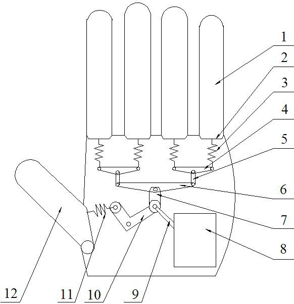
[0022] Embodiment one, such as figure 1 As shown, the linkage mechanism includes a control rod 10 and a control unit that are movably connected to the driving arm 9. The control rod 10 is connected to the knuckle 2 of the thumb 12 through the second spring 11, and the driving arm 9 of the driving machine 8 moves in sequence. The control rod 10 is driven to move, and under the action of the control rod 10, the thumb 12 can smoothly realize bending and stretching. Due to the buffering effect of the second spring 11, the bending and stretching of the thumb 12 has a certain degree of flexibility, so that the thumb 12 has a certain degree of self-adaptive ability, which facilitates the smooth realization of grasping objects.

[0023] The control unit is connected to the knuckle 2 of the finger 1 through the first spring 3, and the control unit includes an active rod 7 that is movably connected with the driving arm 9, a crossbar 6 that is movably connected with the active rod 7, and...

Embodiment 2

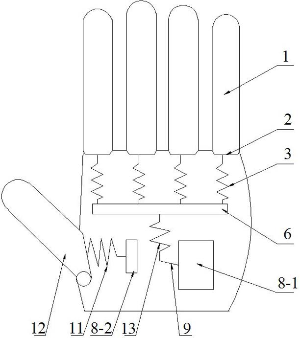
[0025] Embodiment two: if figure 2 As shown, the driving machine 8 includes a first driving machine 8-1 and a second driving machine 8-2, and the driving arm 9 of the first driving machine 8-1 is connected with the cross bar 6 through the third spring 13, so Said crossbar 6 is respectively connected with the knuckles 2 of the four fingers 1 of the bionic hand through the first spring 3 in turn, and under the action of the first driving machine 8-1, the four fingers 1 of the bionic hand can move simultaneously to complete the finger joints 1 of the bionic hand. Under the action of the first spring 3 and the third spring 13, the finger 1 has a certain adaptive ability, so that the degree of bending, stretching and rotation of the finger 1 closely matches the shape of the grasped object.

[0026] The driving arm 9 of the second driving machine 8 - 2 is connected with the knuckle 2 of the thumb 12 through the second spring 11 . Using the second driving machine 8-2 to separately ...


PUM


Abstract

The invention discloses a driving device for a self-adaptive bionic hand, which is applied to the field of research and development of bionic hands. The driving device comprises a linkage mechanism arranged in a palm, a driving device body for driving the linkage mechanism, and knuckles connected with the linkage mechanism, wherein the linkage mechanism is connected with the knuckles through elastic components, and the elastic components comprise a second spring connected with the knuckle of a thumb and first springs connected with the knuckles of fingers. The driving device is simple in structure and novel in design, the self-adaptive characteristic is exerted on flexible grabbing of an object by the fingers, the action of grabbing the shape of the self-adaptive object can be realized, rich grabbing postures are achieved, and smooth grabbing of the object can be achieved according to the shape of the object.

Description

technical field [0001] The invention relates to the field of research and development of bionic hands, in particular to a drive device for self-adaptive bionic hands. Background technique [0002] The bionic hand is one of the important means for patients to take care of themselves after amputation, and has become a new hot product. At present, the design and manufacture of bionic hands and the combination of rigidity and flexibility have been paid attention to. Due to the large number of joints in the bionic hand, an underactuated system is often used for control. Underactuated means that the number of independent drives in the system is less than the number of degrees of freedom. It has the advantages of saving energy, reducing cost, and reducing weight. However, during the grasping process, each finger moves in the same way and lacks flexibility. When picking, the position of the fingers cannot be adjusted in time according to the shape of the object being grasped, that...

Claims


Application Information

Patent Timeline
Patent Type & Authority Applications(China)
IPC IPC(8): B25J15/00B25J15/02B25J15/10A61F2/54
CPCB25J15/0009B25J15/02B25J15/10A61F2/54
Inventor 米召礼
Owner 米召礼
Learn More