Spliced special-shaped concrete filled steel tubular column beam-column connecting joint and construction method thereof

A special-shaped steel pipe and connection node technology, which is applied in the direction of construction and building construction, can solve the problems of uneven surface of special-shaped columns and joints, and difficulty in guaranteeing the welding quality of cold-formed areas, so as to improve welding quality, standardization and production. The effect of industrialization and convenient positioning

Pending Publication Date: 2020-12-25
CHONGQING UNIV +1
View PDF0 Cites 3 Cited by
  • Summary
  • Abstract
  • Description
  • Claims
  • Application Information

AI Technical Summary

Problems solved by technology

[0003] In view of the above-mentioned deficiencies in the prior art, the purpose of the present invention is to provide a spliced ​​special-shaped steel pipe concrete column-beam-column connection node and its construction method to solve the problem that the welding quality of the cold-formed area is difficult to guarantee in the prior art, and the surface of the special-shaped column and the joint Problems with uneven surfaces

Method used


Image

  • Spliced special-shaped concrete filled steel tubular column beam-column connecting joint and construction method thereof
  • Spliced special-shaped concrete filled steel tubular column beam-column connecting joint and construction method thereof
  • Spliced special-shaped concrete filled steel tubular column beam-column connecting joint and construction method thereof

Examples


Embodiment 1

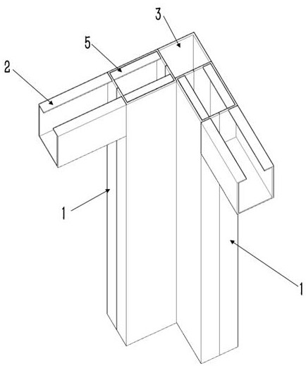
[0029] Embodiment 1: see figure 1 , a splicing special-shaped steel pipe concrete column beam-column connection node, including a plurality of steel pipe columns arranged in the vertical direction, the steel pipe columns are formed by connecting two channel steels 1, wherein the notches of the two channel steels are arranged opposite to each other, And connected to form a steel pipe column, multiple steel pipe columns are combined to form a combined special-shaped column, the two ends of the slots of the two channel steels are aligned and connected by welding, so that the two channel steels form a composite column with a rectangular tubular structure. The adjacent and parallel sides of two adjacent steel pipe columns are misplaced so that the two sides have overlapped parts, and the overlapped parts are fixedly connected together by welding.

[0030] Wherein, a plurality of steel corbels 2 perpendicular to the outer surface of the steel pipe column are also arranged on the ste...

Embodiment 2

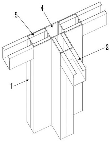
[0033] Example 2: see figure 2, the same basic structure as in Example 1, except that the combined special-shaped column includes three steel pipe columns, and the three steel pipe columns are distributed in a T shape. Two of the steel pipe columns are located on the same plane, and a gap is formed between the two steel pipe columns, and the other steel pipe column extends into the gap from one side of the gap and is fixedly connected with the two steel pipe columns. The connector is a U-shaped member 4, the open side of the U-shaped member extends into the gap from the other side of the gap, and is fixedly connected with two steel pipe columns located on the same plane, and the closed side of the U-shaped member is located on the same plane. The two steel pipe columns of the plane are flush. In actual construction, the U-shaped member can be made of U-shaped steel or channel steel, and the three steel pipe columns and the U-shaped member are enclosed to form a rectangular t...

Embodiment 3

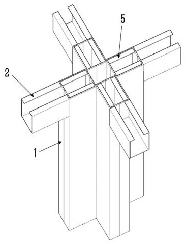
[0034] Embodiment 3: see image 3 , the basic structure is the same as that of Example 1, except that the combined special-shaped column includes four steel tube columns, which are distributed in a cross shape. Among them, two of the four steel pipe columns are located on the same plane, and a gap is formed between the two steel pipe columns located on the same plane, and the other two steel pipe columns extend into the gap and are fixedly connected with the two steel pipe columns. In actual construction, one side of the four steel pipe columns is enclosed to form a tubular space, and concrete is poured in the tubular space and the steel pipe columns to form a cross-shaped special-shaped steel pipe concrete column, which can make the concrete and steel structure better. connected into one.

[0035] A construction method for splicing special-shaped concrete-filled steel pipe column-beam-column joints, adopting splicing special-shaped steel pipe-column-beam-column joints as des...


PUM


Abstract

The invention discloses a spliced special-shaped concrete filled steel tubular column beam-column connecting joint and a construction method thereof. The spliced special-shaped concrete filled steel tubular column beam-column connecting joint comprises a plurality of steel tubular columns arranged in the vertical direction, wherein each steel tubular column is formed by connecting two pieces of channel steel; and notches of the two pieces of channel steel are oppositely arranged and combined and welded to form the steel tubular column, and the plurality of steel tubular columns are combined toform a combined special-shaped column. The two adjacent and parallel sides of every two adjacent steel tubular columns are arranged in a staggered mode and welded and fixed together. The channel steel serves as basic units to be spliced to form the steel tubular columns, the number of selected component types is small, standardization and production industrialization of components are improved, asteel cold bending area can be effectively avoided, stress concentration of the cold bending area is avoided, the welding quality is effectively improved, and meanwhile positioning is convenient; andthe surfaces of the spliced special-shaped concrete filled steel tubular columns and a joint area are smooth, the attractiveness of a building is guaranteed, and the extra cost of building decorationis reduced.

Description

technical field [0001] The invention relates to the technical field of steel structure construction engineering, in particular to a connection node for splicing special-shaped steel pipe concrete column-beam-column and a construction method thereof. Background technique [0002] At present, compared with the traditional square and rectangular cross-section frame columns, T-shaped, L-shaped and cross-shaped columns are represented by special-shaped cross-section columns. and improve the utilization of building space. Reinforced concrete special-shaped columns are widely used in the prior art, but their further popularization and application are restricted due to problems such as low bearing capacity, insufficient use of material strength, and difficulties in on-site concrete pouring. However, most of the existing special-shaped steel pipe columns are formed by continuous welding of multiple square pipes, rectangular pipes, U-shaped steel or channel steel. , Most of the spec...

Claims


Application Information

Patent Timeline
Patent Type & Authority Applications(China)
IPC IPC(8): E04B1/30E04B1/58
CPCE04B1/30E04B1/58
Inventor 程睿胥兴夏双武崔佳胡超陈杰
Owner CHONGQING UNIV
Why Eureka
Try Eureka