
Engine front end water outlet structure

A water outlet structure, engine technology, applied in engine components, engine cooling, machine/engine, etc., to achieve the effect of reducing cost and weight, reducing layout difficulty, and facilitating processing

Pending Publication Date: 2020-12-25
GUANGXI YUCHAI MASCH CO LTD
View PDF3 Cites 0 Cited by
  • Summary
  • Abstract
  • Description
  • Claims
  • Application Information

AI Technical Summary

Problems solved by technology

[0007] However, for an engine with an overhead camshaft arranged on the cylinder head and driven by a chain, because the chain lubricates oil splashes, a gear chamber cover must be used to seal the front end of the cylinder head. Directly open holes on the top to realize front-end water outlet

Method used


Image

  • Engine front end water outlet structure
  • Engine front end water outlet structure
  • Engine front end water outlet structure

Examples


Embodiment 1

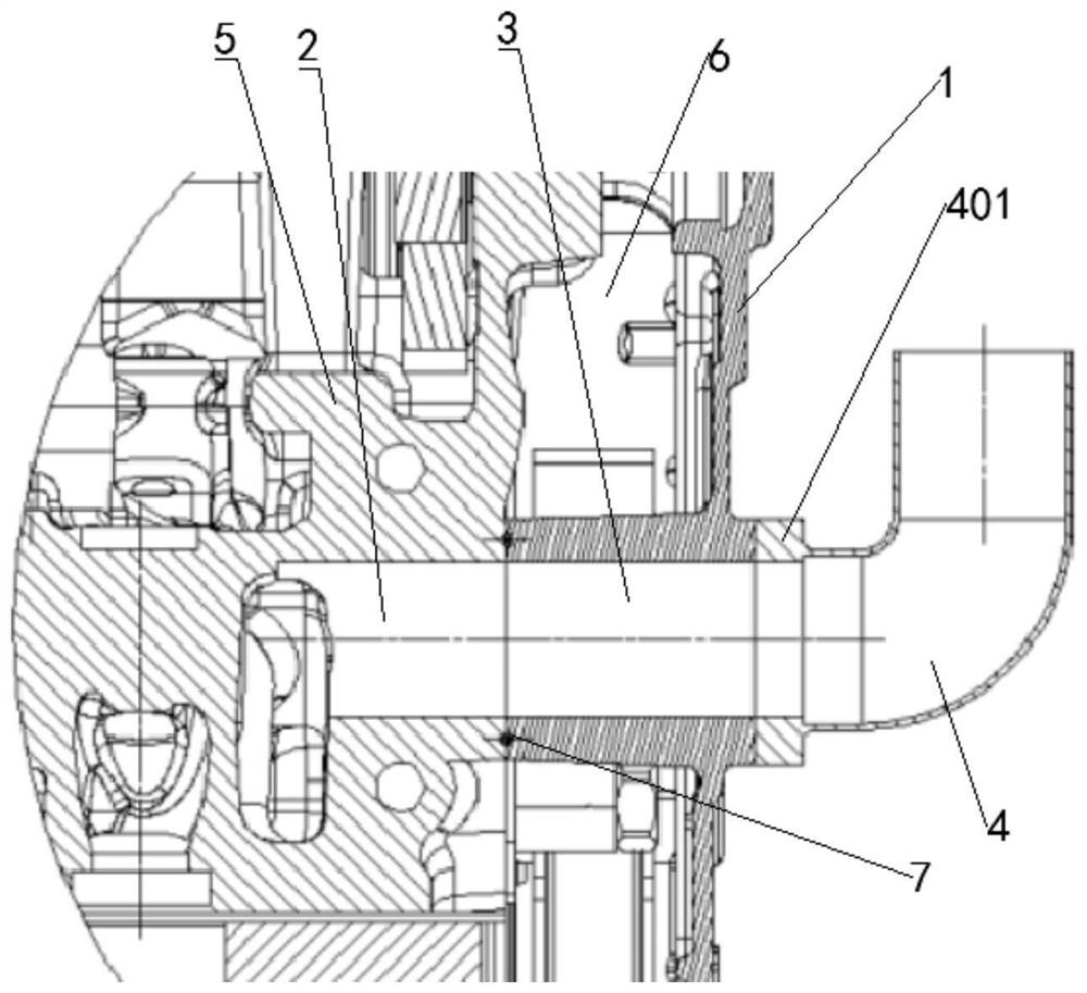
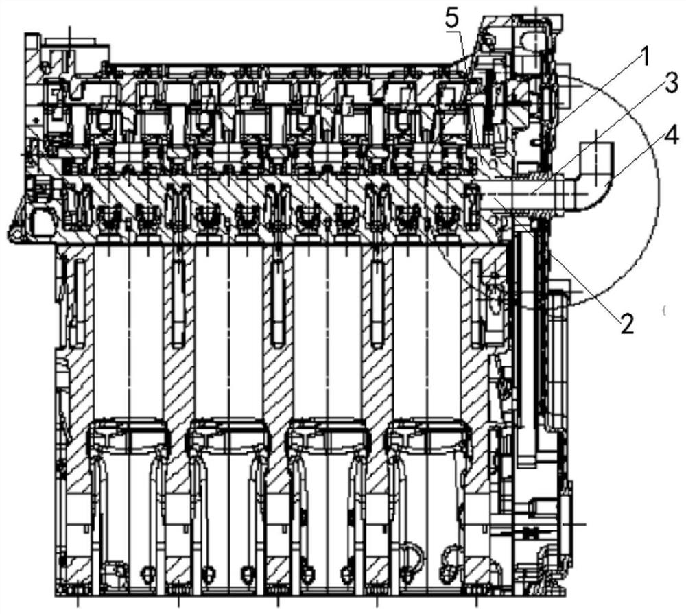
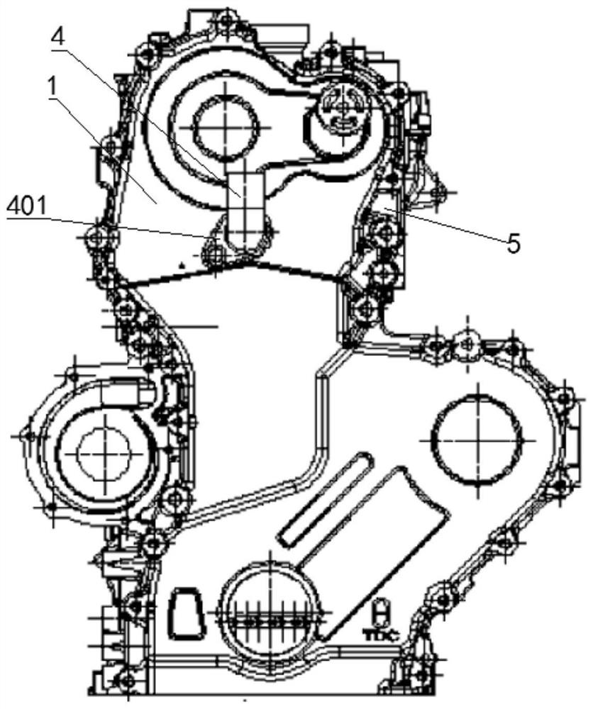
[0029] Such as Figure 1 ~ Figure 3 As shown, a water outlet structure at the front end of the engine includes a gear chamber cover 1 arranged on the front end surface of the cylinder head 5 and the outer edge of the engine gear chamber 6 for sealing fit, and a first water jacket communicating with the inside of the cylinder head 5 and the cylinder head 5 is provided. A water outlet channel 2, the gear chamber cover 1 is provided with a second water outlet channel 3 communicating with the first water outlet channel 2, and the left end surface of the second water outlet channel 3 is in sealing fit with the engine gear chamber 6 , the right side of the second water outlet channel 3 is connected to the water outlet joint 4 arranged outside the front end of the cylinder block.

[0030] The flow process of cooling liquid of the present invention is as follows:

[0031] The engine water outlet is integrated on the gear chamber cover 1 to realize the water outlet function at the fro...

Embodiment 2

[0034] In this implementation, the front end and the rear end of the engine are defined as: the end of the crankshaft where the pulley is installed is the front end of the engine, and the end where the flywheel is installed is the rear end of the engine.

[0035] Such as Figure 1 ~ Figure 3 As shown, a water outlet structure at the front end of the engine includes a gear chamber cover 1 arranged on the front end of the cylinder head 5 and the outer edge of the engine gear chamber 6 to seal and cooperate. The gear chamber cover 1 seals the front end of the cylinder head, and the gear chamber cover 1 1. It is used to seal the chains and gears in the gear chamber and prevent the lubricating oil from splashing; the first water outlet channel 2 communicating with the water jacket of the cylinder head 5 is provided inside the cylinder head 5, and the first water outlet channel 2 is used to drain the water jacket The coolant is drawn out, the gear chamber cover 1 is provided with a ...


PUM


Abstract

The invention provides an engine front end water outlet structure. The structure comprises a gear chamber cover and a first water outlet channel, wherein a gear chamber cover is arranged on the frontend face of an air cylinder cover and matching the outer edge of an engine gear chamber in a sealed mode, the gear chamber cover seals the front end of the air cylinder cover, and the gear chamber cover is used for sealing a chain and a gear in a gear chamber and preventing lubricating oil from splashing; the first water outlet channel is arranged inside the air cylinder cover and communicates with an air cylinder cover water jacket and used for leading out a cooling liquid in the water jacket, a second water outlet channel communicating with the first water outlet channel is formed in the gear chamber cover in a penetrating mode, the left side end face of the second water outlet channel is in sealing fit with the engine gear chamber, and the right side of the second water outlet channel is connected to a water outlet connector arranged outside the front end of an air cylinder body. An engine water outlet is integrated on the gear chamber cover, a water outlet function of the engine front end is achieved, the overall appearance of an engine is improved, the arrangement difficulty of the engine is reduced, and a cost and a weight of the engine are reduced.

Description

technical field [0001] The invention belongs to the technical field of automobiles, and in particular relates to a water outlet structure at the front end of an engine. Background technique [0002] The water inlet mode of the engine cooling system in the prior art often adopts front-end water inlet and rear-end water outlet. The usual way is to open holes from the rear end or side of the cylinder head, and then lead the water to the front-end water outlet of the engine through a longer connecting pipe. [0003] Such as the new gasoline engine disclosed in Chinese patent CN2623889Y, including cylinder head, cylinder block, crank-piston connecting rod mechanism, gas distribution mechanism, intake and exhaust system, etc., it is characterized in that the cylinder head is designed as two bodies up and down, and double overhead camshaft mounting holes It is set on the joint surface of the upper and lower bodies; the water jacket is designed for water inlet at the front end and w...

Claims


Application Information

Patent Timeline
IPC IPC(8): F02F1/10F02F1/14F02F7/00F02F11/00F01P3/20
CPCF02F1/10F02F1/14F02F7/007F02F11/002F02F11/00F01P3/20
Inventor 陈晓克樊心龙蒙小聪
Owner GUANGXI YUCHAI MASCH CO LTD
Learn More