Pneumatic surge suppressor

A surge suppressor, suppressor technology, applied in pump control, machine/engine, liquid fuel engine, etc., to solve problems such as leakage, cross-contamination, etc.

Active Publication Date: 2020-12-25
GRACO INC
View PDF12 Cites 0 Cited by
  • Summary
  • Abstract
  • Description
  • Claims
  • Application Information

AI Technical Summary

Problems solved by technology

If the diaphragm ruptures, cross-contamination and leakage may occur

Method used


Image

  • Pneumatic surge suppressor
  • Pneumatic surge suppressor
  • Pneumatic surge suppressor

Examples


Embodiment Construction

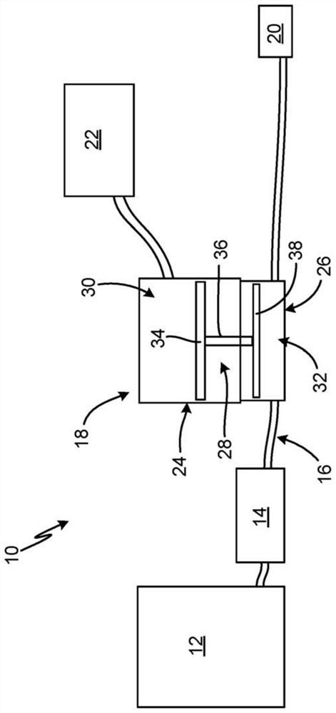
[0015]figure 1 It is a schematic block diagram of the fluid processing system 10. The fluid treatment system 10 includes a reservoir 12, a pump 14, a fluid line 16, a surge suppressor 18, an outlet 20, and a working fluid source 22. The surge suppressor 18 includes an air housing 24, a process housing 26, a suppressor mechanism 28, a working fluid chamber 30, and a process fluid chamber 32. The suppressor mechanism 28 includes a pressurizing member 34, a shaft 36, and a pressure control member 38.

[0016]The fluid treatment system 10 is configured to provide a process fluid at a certain pressure at the outlet 20. In some examples, the process fluid is paint, such that the fluid treatment system 10 is a paint treatment system. In some examples, the process fluid is a lubricant, such that the fluid treatment system 10 is a lubricant treatment system. In some examples, among other options, the process fluid is an automotive fluid, such as oil, coolant, cleaning fluid, and transmission fl...


PUM


Abstract

A surge suppressor includes a boost mechanism configured to balance pressures between a working fluid and a process fluid. The boost mechanism includes a boost member that is acted on by a charge pressure of the working fluid. A shaft extends from the boost member to a pressure control member bounding the process fluid and acting on the process fluid. The boost member can have a larger effective area than the pressure control member to provide a pressure multiplication between the charge pressure and the process fluid pressure. In addition, pressure control valves are mounted to an air housingand actuated open by the boost mechanism. Actuating one of the pressure control valves open increases the charge pressure. Actuating the other pressure control valve open decreases the charge pressure.

Description

[0001]Cross references to related applications[0002]This application claims the priority of U.S. Provisional Application No. 62 / 676,413 filed on May 25, 2018, entitled "PNEUMATIC SURGESUPPRESSOR", the entire disclosure of which is incorporated herein by reference. .Background technique[0003]The present disclosure relates generally to fluid displacement. More specifically, the present disclosure relates to fluid pumps and vibration attenuation.[0004]Surge suppressors are used in many industries to help attenuate pressure changes and spikes in fluid handling systems. In paint circulation systems, surge suppressors are used to attenuate pressure pulsations generated by the output of reciprocating pumps during the transition between pump strokes.[0005]Pneumatic surge suppressors usually include a diaphragm that is disposed between a working fluid (such as compressed air) on one side of the diaphragm and a process fluid (such as paint) on the other side of the diaphragm. This design inhe...

Claims


Application Information

Patent Timeline
Patent Type & Authority Applications(China)
IPC IPC(8): F04B11/00F04B39/10F04B49/08
CPCF04B11/0016F04B39/10F04B49/08F04B2205/05F04B45/053F04B53/001F04B45/0533F04B45/0536F04B49/22F04B53/06F04B53/129F04B2205/03F04B11/0008
Inventor 蒂姆西·S·罗曼
Owner GRACO INC
Why Eureka
Try Eureka