
Ball mill for graphene production

A technology for graphene and balls, which is applied in the field of ball mills for graphene production, can solve the problems of reducing the contact area between iron balls and the inner wall of hollow shafts, affecting the grinding effect of iron balls, and reducing the effect of crushing materials, so as to reduce impact force, Enhance fit and grip, enhance the effect of surface tension

Inactive Publication Date: 2020-12-29
牛虎
View PDF8 Cites 4 Cited by
  • Summary
  • Abstract
  • Description
  • Claims
  • Application Information

AI Technical Summary

Problems solved by technology

[0002] The ball mill adopts the method of rotation, so that the material enters the hollow shaft, and the material is rubbed and crushed with the rotation of the iron ball. After the gravity is greater than the centrifugal force, the iron ball breaks away from the inner wall of the hollow shaft and rolls down. The ball mill rotates, and the steel ball slides and grinds the material, making the material smaller and smaller, but the impact force of the iron ball projectile easily makes the material crushed on the inner wall of the hollow shaft, so the iron ball is easy to rub and grind the crushed material at the bottom, The contact area between the iron ball and the inner wall of the hollow shaft is reduced, so that the iron ball does not roll down following the projection of the hollow shaft, which reduces the effect of crushing materials, and the iron ball impacts the inner wall of the hollow shaft during the throwing process, which easily deforms the inner wall of the hollow shaft. Affect the grinding effect of iron balls on materials

Method used


Image

  • Ball mill for graphene production
  • Ball mill for graphene production
  • Ball mill for graphene production

Examples


Embodiment 1

[0023] like Figure 1-Figure 5 Shown:

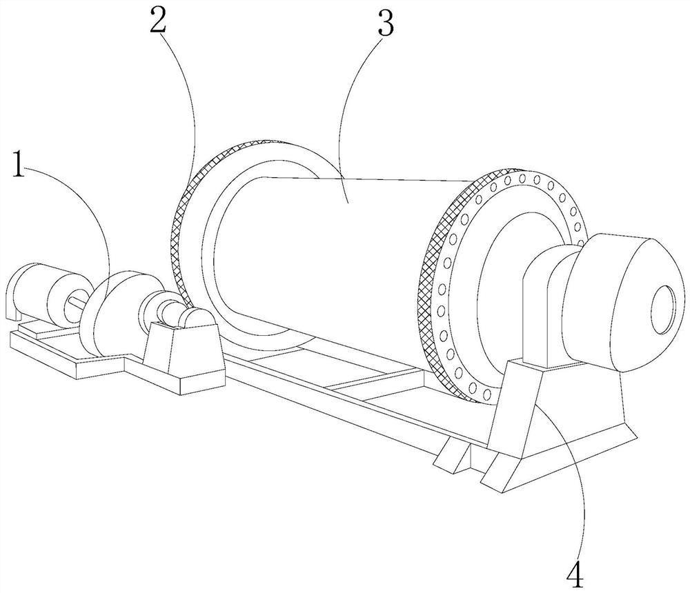
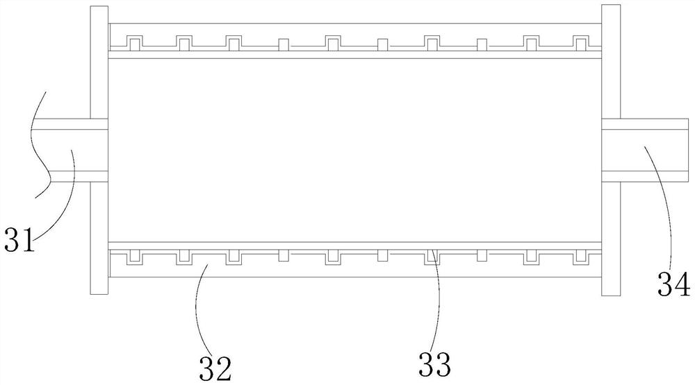
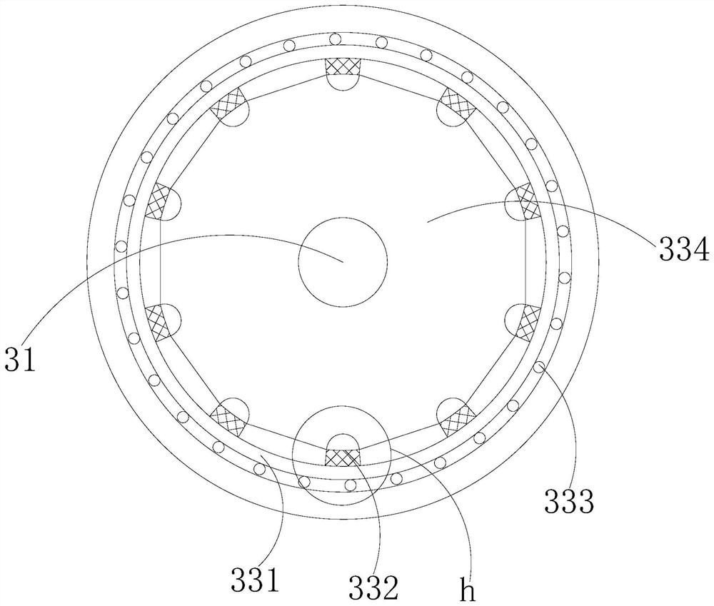
[0024] A kind of ball mill for graphene production of the present invention, its structure comprises motor 1, gear 2, drum mechanism 3, support frame 4, described motor 1 and gear 2 are threadedly matched, and described gear 2 is embedded and fixed on the outer side of drum mechanism 3 , the support frame 4 is located at the lower end of the drum mechanism 3, the drum mechanism 3 is provided with a material inlet 31, a drum 32, a rotating mechanism 33, and a material outlet 34, and the drum 32 is embedded on the outside of the rotating mechanism 33, The material inlet 31 is installed on the left side of the drum 32, the material outlet 34 is embedded on the right side of the drum 32, the material outlet 34 and the material inlet 31 are located on the same central axis, and the drum 32 is located on the support At the upper end of the frame 4, there is a certain gap between the roller 32 and the rotating mechanism 33, the material inlet ...

Embodiment 2

[0031] like Figure 6-Figure 7 Shown:

[0032] Wherein, the force receiving mechanism a1 is provided with a friction mechanism w1, a rubber strip w2, a fan-shaped plate w3, a ball block w4, a hollow ball w5, and a connecting plate w6. The friction mechanism w1 is attached to the outside of the fan-shaped plate w3, and the rubber The strip w2 is embedded between the fan-shaped plates w3, the rubber strip w2 is attached to the outside of the ball block w4, the hollow ball w5 is located at the lower end of the ball block w4, the hollow ball w5 is installed inside the connecting plate w6, and the ball The block w4 is embedded and fixed on the upper end of the connecting plate w6, and the connecting plate w6 is installed in the middle of the welding block a4. The fan-shaped plate w3 is evenly surrounded by a semicircle centered on the ball block w4, and is attached to the outside of the ball block w4. The ball block There is a gap between w4 and the connection plate w6, so that wh...


PUM


Abstract

The invention discloses a ball mill for graphene production. The ball mill structurally comprises a motor, a gear, a rotary drum mechanism and a supporting frame, wherein the motor is in threaded fitwith the gear, the gear is fixedly embedded in the outer side of the rotary drum mechanism, the supporting frame is located at the lower end of the rotary drum mechanism, and the rotary drum mechanismis provided with a feeding port, a roller, a rotating mechanism and a discharging port. According to the ball mill, a rotating ring and balls are in fitting rotation, iron balls are clamped on the side faces of stress mechanisms, after the iron balls fall off under the action of gravity, elastic blocks are compressed when the sliding plates are subjected to the action of the iron balls, so that material grinding is prevented from being hindered by vibration generated by springback, the impact force borne by the sliding plates is reduced, the sliding plates are prevented from deforming due toexcessive stress, and the material grinding effect is prevented from being affected by unevenness of the sliding plate; and bending plates are compressed by the gravity of the iron balls, the surfacetension of the friction plates to fit is enhanced, fan-shaped plates is extruded by fixing rings, hollow balls in the middle of connecting plates are compressed by ball blocks, and meanwhile, a slightinertia force is generated under the fitting pressure, so that the fitting gripping force of friction mechanisms to the iron balls is enhanced.

Description

technical field [0001] The invention relates to the field of graphene processing equipment, in particular to a ball mill for graphene production. Background technique [0002] The ball mill adopts the method of rotation, so that the material enters the hollow shaft, and the material is crushed by friction with the rotation of the iron ball. After the gravity is greater than the centrifugal force, the iron ball breaks away from the inner wall of the hollow shaft and rolls down. The ball mill rotates, and the steel ball slides and grinds the material, making the material smaller and smaller, but the impact force of the iron ball throwing is easy to make the material crush on the inner wall of the hollow shaft, so the iron ball is easy to rub and grind with the crushed material at the bottom, The contact area between the iron ball and the inner wall of the hollow shaft is reduced, so that the iron ball does not roll down following the projection of the hollow shaft, which reduc...

Claims


Application Information

Patent Timeline
Patent Type & Authority Applications(China)
IPC IPC(8): B02C17/10B02C17/18B02C17/22
CPCB02C17/10B02C17/18B02C17/225
Inventor 牛虎
Owner 牛虎
Learn More