Cable production cutting equipment with automatic feeding and discharging function

A technology of automatic loading and unloading, cutting equipment, applied in the field of cable production, can solve problems such as inability to cut cables

Inactive Publication Date: 2020-12-29
湖南新耒传导材料科技有限公司
View PDF1 Cites 3 Cited by
  • Summary
  • Abstract
  • Description
  • Claims
  • Application Information

AI Technical Summary

Problems solved by technology

A cutting device for cable production in the above-mentioned patent has the following disadvantages: the cable can be clamped by the cable clamping mechanism, and then the cable can be cut by a cutter, but after the cutting is completed, the position of the cable needs to be changed again to fix it. fixed, no continuous cutting of the cable

Method used


Image

  • Cable production cutting equipment with automatic feeding and discharging function
  • Cable production cutting equipment with automatic feeding and discharging function
  • Cable production cutting equipment with automatic feeding and discharging function

Examples


Embodiment 1

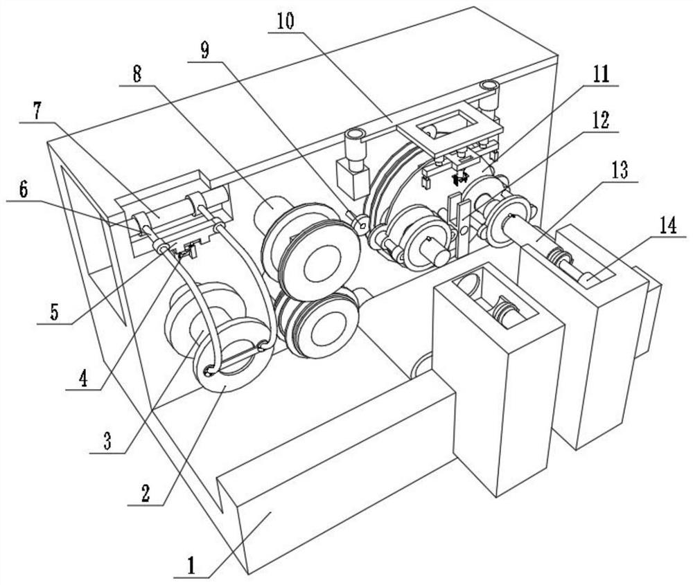
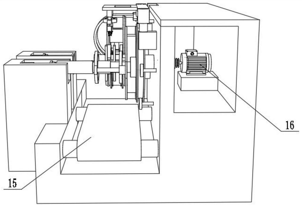
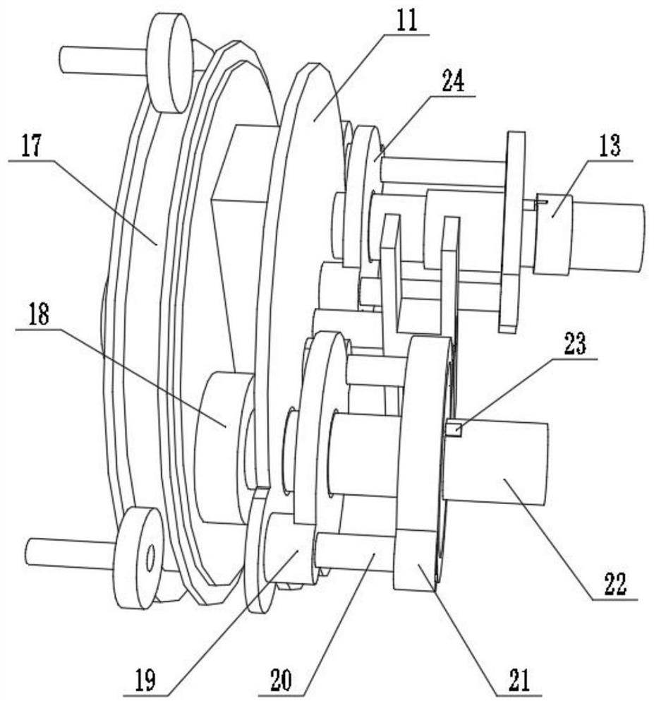
[0036]A cable production and cutting equipment with automatic loading and unloading functions, such asfigure 1 ,2, 3, 4, and 8, including a housing 1 and a reel 13. The inner wall of the housing 1 is rotatably connected with a conversion disk 11, and the inner wall of the housing 1 is fixed with a motor 16 by screws. The output shaft of the motor 16 It is connected to the conversion disk 11 through a coupling. Two connecting posts 19 are welded on both ends of the outer wall of the conversion disk 11. The outer walls of the two connecting posts 19 are fixed with the same connecting disk 24 by screws, and the inner wall of the connecting disk 24 is rotatably connected. The rod 22, the inner wall of the connecting plate 24 is fixed with a motor two 18 by screws, the output shaft of the motor two 18 is connected to the rotating rod 22 through a coupling, and the two ends of the outer wall of the connecting plate 24 are welded with two electric telescopic rods 20, two The outer walls of...

Embodiment 2

[0041]A cable production and cutting equipment with automatic loading and unloading function, in order to facilitate the feeding of cables; such asfigure 1 As shown, the outer wall of the housing 1 is welded with a feeding rod 3, and the outer wall of the housing 1 is welded with a connecting rod 7 that is rotatably connected to the outer wall of the connecting rod 7 with a support frame 6, and the outer wall of the support frame 6 is fixed by screws. The limit baffle 2, the outer wall of the support frame 6 is clamped with a connecting frame 5, the outer wall of the connecting frame 5 is fixed with a hydraulic rod 4 through a hinge, and the other side of the hydraulic rod 4 is connected to one side of the housing 1 through a hinge The outer wall is connected; by setting the feeding rod 3 and the limit baffle 2, the coiled cable is placed on the feeding rod 3, and then the hydraulic rod 4 is controlled to lift the support frame 6, and the limit baffle 2 is stuck in One end of the fe...


PUM


Abstract

The invention discloses cable production cutting equipment with an automatic feeding and discharging function, and relates to the field of cable production. The problem that a cable cannot be continuously cut is solved. The cable production cutting equipment specifically comprises an outer shell and a winding drum. A conversion disc is rotationally connected to the inner wall of one side of the outer shell. Two connecting columns are welded to the two ends of the outer wall of the conversion disc respectively. The outer walls of the two connecting columns are fixedly connected with the same connecting disc through screws, and rotating rods are rotationally connected to the inner wall of the connecting disc. A second motor is fixed to the inner wall of one side of the connecting disc through screws. According to the cable production cutting equipment, the conversion disc and the rotating rods which are fixedly provided with a cable in a rotating mode are arranged, and the winding drum is rotated under the action of a first clamping block and a mounting opening; and then the cable is cut, the cut cable can be pushed out by a circular plate, one end of the remaining cable can be clamped onto the other rotating rod and the winding drum, and then the first motor is started. The conversion disc is rotated to exchange the positions of the two rotating rods, and the step of fixing thecable is repeated, so that continuous cutting of the cable is realized.

Description

Technical field[0001]The invention relates to the field of cable production, in particular to a cable production and cutting equipment with automatic loading and unloading functions.Background technique[0002]A cable is made of one or more mutually insulated conductors and an outer insulating protective layer. It is a wire that transmits power or information from one place to another. It is widely used in power lines and signal lines of power equipment; In the process of cable production, it is often necessary to cut the cable into cables of different lengths according to requirements, so a cable production cutting device is needed.[0003]After searching, the Chinese Patent Application Publication No. CN110216225A discloses a cutting device for cable production, including a processing table, the top of the processing table is provided with a mounting slot, and a screw motor is installed on one outer wall of the processing table , And the output end of the lead screw motor is installed...

Claims


Application Information

Patent Timeline
Patent Type & Authority Applications(China)
IPC IPC(8): B21F11/00B21F1/02B21F23/00B21C47/02
CPCB21C47/02B21F1/026B21F11/00B21F23/00
Inventor 赵峥汤小金孙爱国曾智俊曾小云
Owner 湖南新耒传导材料科技有限公司
Why Eureka
Try Eureka