Substrate glass bait cutting equipment

A technology for cutting equipment and glass, applied in glass manufacturing equipment, glass cutting devices, glass production, etc., can solve problems such as poor cutting, achieve the effects of reducing product loss, improving cutting quality, and expanding packaging technology

Active Publication Date: 2020-06-26
TUNGHSU TECH GRP CO LTD +1
View PDF17 Cites 3 Cited by
  • Summary
  • Abstract
  • Description
  • Claims
  • Application Information

AI Technical Summary

Problems solved by technology

[0003] The purpose of the present disclosure is to provide a substrate glass bait cutting equipment, which can solve the problems of poor

Method used


Image

  • Substrate glass bait cutting equipment
  • Substrate glass bait cutting equipment
  • Substrate glass bait cutting equipment

Examples


Embodiment Construction

[0045] Specific embodiments of the present disclosure will be described in detail below in conjunction with the accompanying drawings. It should be understood that the specific embodiments described here are only used to illustrate and explain the present disclosure, and are not intended to limit the present disclosure.

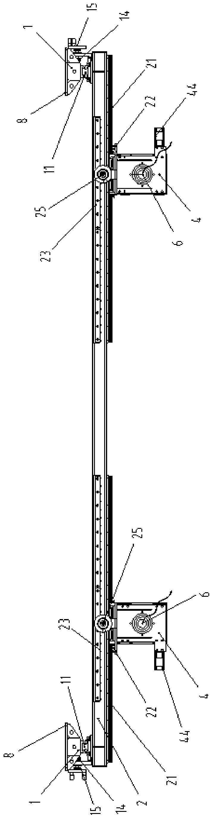
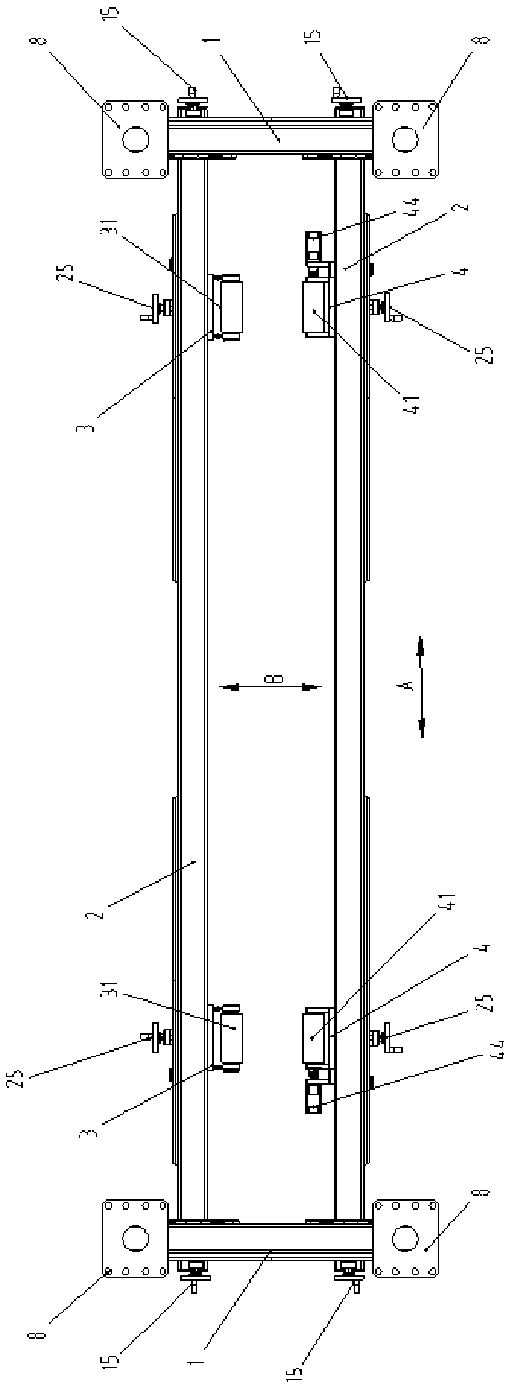
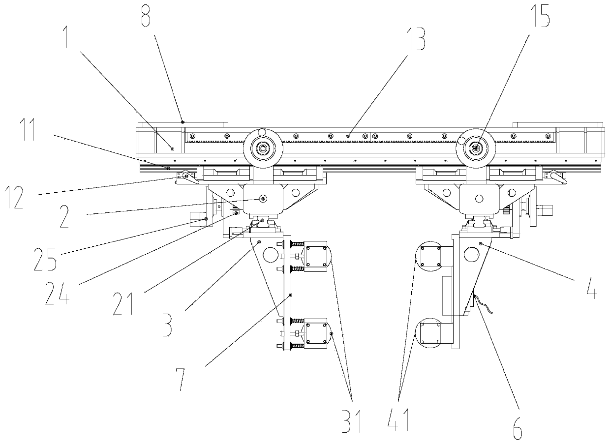
[0046] In the present disclosure, the use of orientation words such as "upper", "lower", "front", "rear", "left", "right" generally refer to the It is defined when the substrate glass bait cutting equipment is working normally. For details, please refer to the drawing direction of the attached drawing. figure 2 The direction marked by the middle arrow A is the left and right direction, figure 2 The direction indicated by the middle arrow B is the front-back direction. In addition, the terms "first", "second", and the like used in the present disclosure are for distinguishing one element from another, and do not have sequence or importance. When the follo...


PUM


Abstract

The invention relates to substrate glass bait cutting equipment, which comprises: two oppositely arranged first mounting beams (1) for fixing the cutting equipment; two second mounting beams (2) arranged between the two first mounting beams in a front-back moving mode and used for loosening or clamping base plate glass (5); two first driving device (3) arranged on one second mounting beam in a left-right moving manner; two second guide devices (4) are arranged on the other second mounting beam in a left-right moving mode, wherein the positions of the first guide devices on the two second mounting beams correspond to the positions of the second guide devices on the two second mounting beams; and a laser generator (6) installed on the second guide device and used for cutting the base plate glass when the base plate glass penetrates through the plane where the first mounting beam and the second mounting beam are located from top to bottom in the vertical state. According to the cutting equipment, base plate glass has excellent cutting quality during bait cutting, and the yield and the production efficiency are improved.

Description

technical field [0001] The present disclosure relates to the field of substrate glass manufacturing, in particular, to a substrate glass bait cutting device. Background technique [0002] In the production process of substrate glass, when it comes to the cutting of substrate glass bait, the cutting process of diamond wheel scribing and breaking is currently used. This cutting process is only suitable for substrate glass with a thickness of 0.2-0.5mm. When the thickness of the glass is When it is less than 0.2mm, the cutting process of diamond wheel scribing and breaking will cause the problem of slivers, which will affect the quality of ultra-thin substrate glass and reduce production efficiency. Secondly, the packaging process of ultra-thin substrate glass is no longer limited to sheet packaging. Due to the softness of ultra-thin substrate glass, it can be packaged in rolls, and the length of each roll can reach more than 100 meters. For substrate glass with longer meters, ...

Claims


Application Information

Patent Timeline
IPC IPC(8): C03B33/02
CPCC03B33/0207Y02P40/57
Inventor 李青李赫然陈肖帆张慧欣毕相群崔海舰
Owner TUNGHSU TECH GRP CO LTD
Why Eureka
Try Eureka