Efficient plastic pipe cutting equipment

A technology for plastic pipes and cutting equipment, applied in metal processing, etc., can solve the problems of low work efficiency, inconvenient adjustment of cutters and clamping parts, etc., and achieve the effects of high work efficiency, increased practicability, and simple operation

Inactive Publication Date: 2021-04-06
贵州永丰科技管业有限公司
View PDF13 Cites 3 Cited by
  • Summary
  • Abstract
  • Description
  • Claims
  • Application Information

AI Technical Summary

Problems solved by technology

[0005] The purpose of the present invention is to provide a high-efficiency plastic pipe cutting equipment in order to solve the technical problems of inconvenient adjustment of the cutter and the clamping part of the existing cutting equipment and low work efficiency

Method used


Image

  • Efficient plastic pipe cutting equipment
  • Efficient plastic pipe cutting equipment
  • Efficient plastic pipe cutting equipment

Examples


Embodiment 1

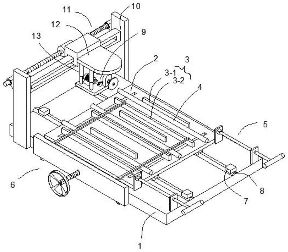
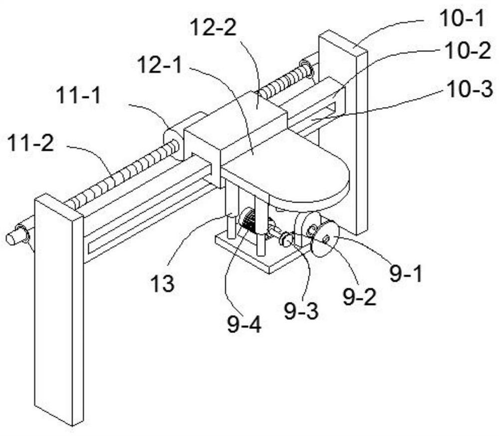
[0031] Such as Figures 1 to 3 As shown, the present embodiment provides a high-efficiency plastic pipe cutting equipment, including a square base 1 and a door-shaped knife mounting frame 10 arranged above one end of the square base 1. The door-shaped knife mounting frame 10 is provided with a The tool mounting seat 12 that moves at the top of the tool mounting frame 10, the door-shaped tool mounting frame 10 is provided with a linear drive mechanism 11 that drives the tool mounting seat 12 to move, and a horizontal plate is connected below the tool mounting seat 12 through a telescopic mechanism 13. The horizontal plate is provided with a compound cutter mechanism 9, and the square base 1 is provided with a mobile platform 2, and multiple groups of adjustable clamps for clamping the plastic pipe 4 to be cut are arranged side by side on the mobile platform 2. Component 3, the square base 1 is provided with a distance adjustment mechanism 6 capable of synchronously adjusting th...

Embodiment 2

[0037] This embodiment is further optimized on the basis of embodiment 1, specifically:

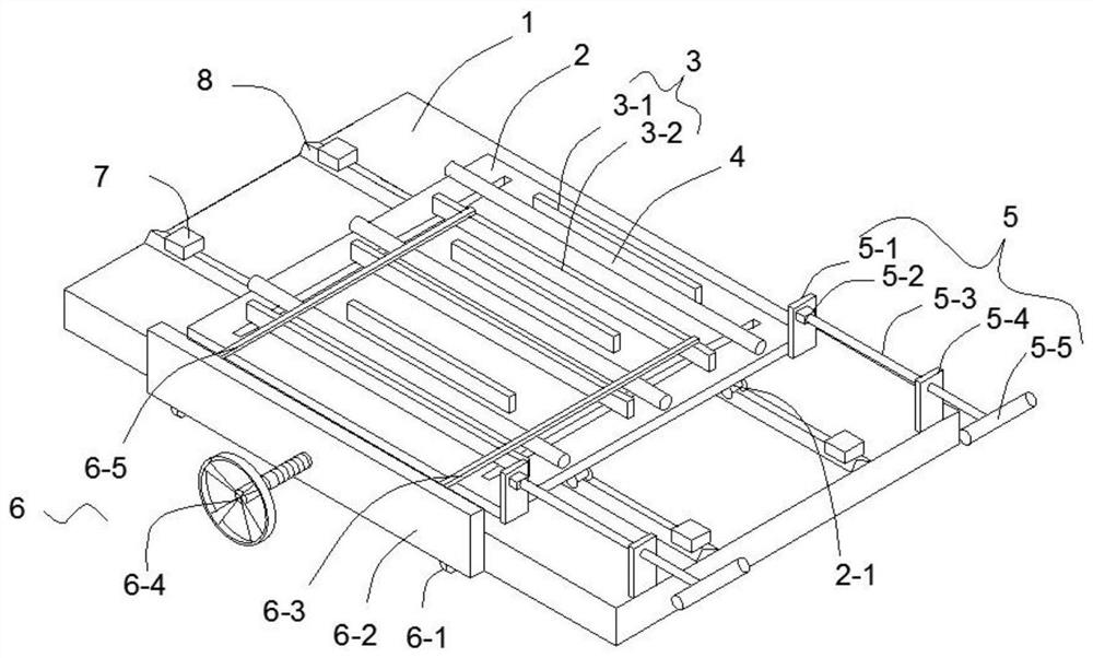
[0038] The square base 1 is provided with two guide rails 8 in parallel according to the length direction, the mobile platform 2 can reciprocate along the two guide rails 8, and the square base 1 is provided with a driving assembly for driving the square base 1 to reciprocate Each set of adjustable clamping components 3 includes a fixed clamping block 3-1 and a movable clamping block 3-2 arranged along the length direction of the square base 1 and parallel to each other, and the corresponding fixed clamping block 3-1 and movable clamping block 3-1 The distance between the clamping blocks 3-2 can be adjusted, and both ends of the mobile platform 2 are provided with limiting grooves 2-2 which are orthogonal to the movable clamping block 3-2 and limit the reciprocating movement direction of the movable clamping block 3-2, The distance adjusting mechanism 6 is fixedly connected to the top of ...


PUM


Abstract

The invention discloses efficient plastic pipe cutting equipment, and relates to the technical field of cutting. The efficient plastic pipe cutting equipment comprises a square base and a door-shaped cutter mounting frame arranged above one end of the square base, wherein a cutter mounting seat capable of moving along the top of the door-shaped cutter mounting frame is arranged on the door-shaped cutter mounting frame; a linear driving mechanism used for driving the cutter mounting base to move is arranged on the door-shaped cutter mounting frame; a horizontal plate is connected with the lower part of the cutter mounting base through a telescopic mechanism; a composite cutter mechanism is arranged on the horizontal plate; a moving platform is arranged on the square base; a plurality of groups of adjustable clamping assemblies used for clamping to-be-cut plastic pipes are parallelly arranged on the moving platform; and a distance adjusting mechanism capable of synchronously adjusting the clamping distances of all the groups of adjustable clamping assemblies is arranged on the square base. The efficient plastic pipe cutting equipment has the advantages that the structure is simple, as well as the clamping distances and the cutting heights are convenient to adjust.

Description

technical field [0001] The invention relates to the technical field of cutting, more specifically to the technical field of high-efficiency plastic pipe cutting equipment. Background technique [0002] As a special equipment for material transportation, plastic pipes are widely used in machinery, petroleum, chemical industry, metallurgy and other industries, and play an important role in modern industrial production and people's lives. The waste pipes produced in the production process of plastic pipes must be cut off during the recycling process. At present, in addition to cutting with planetary saws on the production line, they are also cut with disc saws or cut with the principle of hydraulic transmission guillotine. [0003] The patent application number is "CN201821560790.9" and the patent name is "a plastic pipe cutting machine". Set on the base, the roller assembly is arranged on the support frame, and the support frame is provided with a chute, and there are multipl...

Claims


Application Information

Patent Timeline
Patent Type & Authority Applications(China)
IPC IPC(8): B26D1/18B26D3/16B26D7/02B26D7/20
CPCB26D1/18B26D3/16B26D3/001B26D7/02B26D7/20B26D2007/013
Inventor 任良安
Owner 贵州永丰科技管业有限公司
Why Eureka
Try Eureka