Heat input adjustable consumable electrode arc additive manufacturing method and device

A melting electrode and heat input technology, applied in the field of additive manufacturing, can solve the problems of affecting the welding quality, not being able to combine well, reducing the deposition efficiency, etc., to solve the heat accumulation and heat shortage, avoid heat accumulation and heat shortage, The effect of improving the forming quality

Active Publication Date: 2020-12-29
NANJING UNIV OF SCI & TECH
View PDF13 Cites 3 Cited by
  • Summary
  • Abstract
  • Description
  • Claims
  • Application Information

AI Technical Summary

Problems solved by technology

When the heat input is too large and the additive current needs to be reduced, the corresponding wire feeding speed will decrease accordingly, resulting in a decrease in the deposition efficiency; when the deposition amount is increased to increase the wire feeding speed, the additive current will also increase. Excessive heat input leads to poor forming quality
[0004] At present, there are many researches on arc additive materials, but there are few methods and devices that can automatically increase or decrease the heat input according to the temperature of the workpiece for melting electrode arc additive materials.
In 2013, Chen Shujun, Zhang Liang, Bai Lilai, Men Guangqiang, Sheng Shan, Gong Jinlong and others from Beijing University of Technology published the invention patent CN 103521885A "Welding method for double-wire indirect arc alternate bypass" conceived a The welding method of double-wire indirect arc alternate bypass, specifically: in the provided method, two welding torches are used to form two arc circuits of main circuit + bypass and main circuit, and the arc is made to go back and forth between these two circuits through the reversing switch transformation, in order to reduce welding heat input while increasing deposition amount in this way, so as to realize separate adjustment of deposition amount and heat input, although the method provided by this invention can achieve Reduce welding heat input, but this invention cannot effectively solve the problem of increasing the heat input under the premise of ensuring that the amount of deposition remains unchanged, so as to solve the problem that the molten pool cannot spread due to the low substrate temperature and fast heat dissipation at the beginning of welding
The disadvantage of the method provided by this invention is: when the amount of welding deposition remains unchanged and the heat input is reduced, the reversing switch switches the circuit to the main circuit + bypass circuit to reduce the heat input, and the laser heat source at this time is due to the need The bombardment of the droplet promotes its transition, so its energy cannot be too small or zero, which is in contradiction with the requirements of ensuring that the welding deposit remains unchanged and reducing heat input
At the same time, due to the interference between the laser and the arc and the difference in the heating area of ​​the two heat sources, they cannot be well combined, which affects the welding quality

Method used


Image

  • Heat input adjustable consumable electrode arc additive manufacturing method and device
  • Heat input adjustable consumable electrode arc additive manufacturing method and device
  • Heat input adjustable consumable electrode arc additive manufacturing method and device

Examples


Embodiment 1

[0035] Take the example of adding a high-strength steel straight wall body with length 110mm×width 8mm×height 80mm on a steel plate with length 180mm×width 120mm×height 10mm.

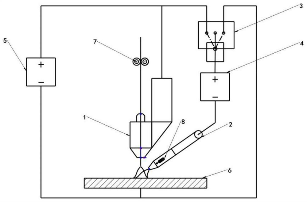
[0036] Such as figure 1Shown is a schematic structural view of the device. The figure includes melting electrode welding torch 1 , melting electrode welding power supply 5 , melting electrode wire feeder 7 , TIG welding torch 2 , TIG welding power supply 4 , circuit intelligent switcher 3 and temperature sensor 8 . Among them, the melting electrode welding torch 1, the melting electrode welding power supply 5 and the workpiece are connected in series to form a melting electrode circuit; the melting electrode welding power supply, TIG welding power supply, TIG welding torch, and workpiece are connected in series to form a non-melting electrode bypass arc circuit; TIG welding torch 2, TIG welding power supply 4 and the workpiece are connected in series to form a non-melting electrode arc circuit. The th...

Embodiment 2

[0044] Take the example of adding an 80mm long x 80mm wide x 80mm high nitrogen steel block on a steel plate with a length of 150mm x width of 150mm x height of 10mm.

[0045] This embodiment 2 adopts such as figure 1 The device structure shown. The figure includes melting electrode welding torch 1 , melting electrode welding power supply 5 , melting electrode wire feeder 7 , TIG welding torch 2 , TIG welding power supply 4 , circuit intelligent switcher 3 and temperature sensor 8 . Among them, the melting electrode welding torch 1, the melting electrode welding power supply 5 and the workpiece are connected in series to form a melting electrode circuit; the melting electrode welding power supply, TIG welding power supply, TIG welding torch, and workpiece are connected in series to form a non-melting electrode arc bypass; TIG welding torch 2 and TIG welding power supply 4 And the workpiece is connected in series to form a non-melting electrode arc circuit. The three circuits...


PUM

PropertyMeasurementUnit
tensile strengthaaaaaaaaaa

Abstract

The invention discloses a heat input adjustable consumable electrode arc additive manufacturing method and device. In the device, a consumable electrode welding gun, a consumable electrode welding power supply and a workpiece are connected in series to form a consumable electrode arc loop of a consumable electrode arc additive. A TIG welding gun, a TIG welding power supply and the workpiece are connected in series to form a non-consumable electrode arc loop. The TIG welding gun, the consumable electrode welding gun and the TIG power supply are connected in series to form a bypass arc loop. Theconsumable electrode loop is associated with the non-consumable electrode loop and the bypass arc loop through an intelligent circuit switcher. The TIG welding gun is provided with a temperature sensor, the temperature sensor is connected with the intelligent circuit switcher, and the intelligent circuit switcher correspondingly adjusts current according to received temperature signals. By meansof the provided method and device, the problem about decoupling of the relation between consumable electrode arc additive heat input and the deposition amount is solved, regulation and control of theconsumable electrode arc additive heat input are achieved on the premise that the deposition efficiency is not changed, heat accumulation and heat insufficiency in the additive process are avoided, and the forming quality of an additive piece is improved.

Description

technical field [0001] The invention belongs to the technical field of additive manufacturing, and in particular relates to a method and device for adding materials by melting electrode arc with adjustable heat input, which is used to solve the problem of poor forming of workpieces caused by excessive or too small heat input in the additive manufacturing process . Background technique [0002] Additive manufacturing technology is based on the idea of ​​discrete-stacking, driven by three-dimensional data of parts, and adopts the method of accumulating materials layer by layer to realize the rapid prototyping of solid parts. The processing process is roughly as follows: first, according to the requirements, use the computer 3D drawing software to draw the 3D image of the part to be processed; secondly, slice the drawn 3D part diagram in a certain way to obtain the 3D data of the part; The obtained 3D data of the parts is imported into the robot operating system, and the robot...

Claims


Application Information

Patent Timeline
Patent Type & Authority Applications(China)
IPC IPC(8): B23K9/133B23K9/167B23K9/173B23K9/10B23K9/32B33Y10/00B33Y30/00B33Y40/00
CPCB23K9/133B23K9/167B23K9/173B23K9/10B23K9/32B33Y10/00B33Y30/00B33Y40/00
Inventor 杨东青王小伟金鸣李晓鹏范霁康黄勇彭勇王克鸿周琦
Owner NANJING UNIV OF SCI & TECH
Why Eureka
Try Eureka