
Eureka
For R&D, Eureka makes reading and utilizing patents & technical documents easy.
Eureka AIR
Designed for self-driven R&D workflows. Generate viable solutions, solve complex R&D challenges, empower your innovation with AI.

Eureka Materials
Designed for material experts only. Revolutionize your material R&D, from search, analyze, to developing new materials.

TechResearch
Generate reliable direction feasibility study reports for your R&D in just a few steps.

TechSeek
Discover and master advanced knowledge NOW. Basics, ideas, possibilities, all at once.

TechMind
As an expert in R&D Theories, TechMind can generates customized viable solutions instantly.

TechRisk
Analyze your overall solution with one click, know your potential R&D risks in advance.

TechMonitor
Get weekly tech updates, stay abreast of the latest tech innovations and key insights.
Laser machine capable of achieving automatic product feeding
An automatic feeding, laser machine technology, applied in welding equipment, laser welding equipment, metal processing equipment and other directions, can solve the problems of slow cutting production, unable to ensure product quality, unable to meet the precise alignment of cutting positions, etc., to save manpower, The effect of increasing productivity
- Summary
- Abstract
- Description
- Claims
- Application Information
AI Technical Summary
Problems solved by technology
Method used
Image

Examples
Embodiment 1
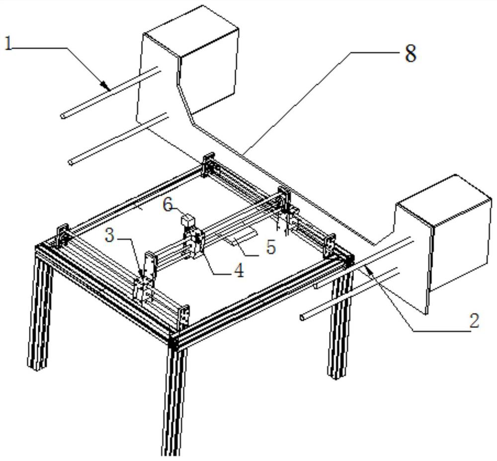
[0030] A laser machine for automatic feeding of products, such as figure 1 As shown, it includes a frame 8, a material belt traction assembly located on the frame 8, a product conveying material belt 7 located on the material belt traction assembly, a laser machine cutting assembly located on the table of the frame 8, And the material belt positioning mold 5 located on the table; the conductive foam 9 to be cut is fixed on the product conveying material belt 7, and is periodically distributed; the product conveying material belt 7 is provided with periodically distributed small holes .
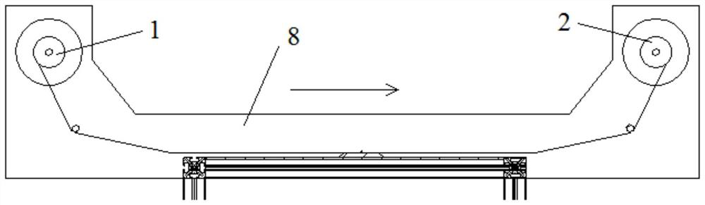
[0031] The strip traction assembly includes a feed shaft 1 and a take-up shaft 2 arranged on both sides of the table, a first guide wheel arranged on one side of the feed shaft 1 and a second guide wheel arranged on one side of the take-up shaft 2, the first guide The distance between the product conveying material belt 7 between the wheel and the second guide wheel and the mold base 51 match...
Embodiment 2
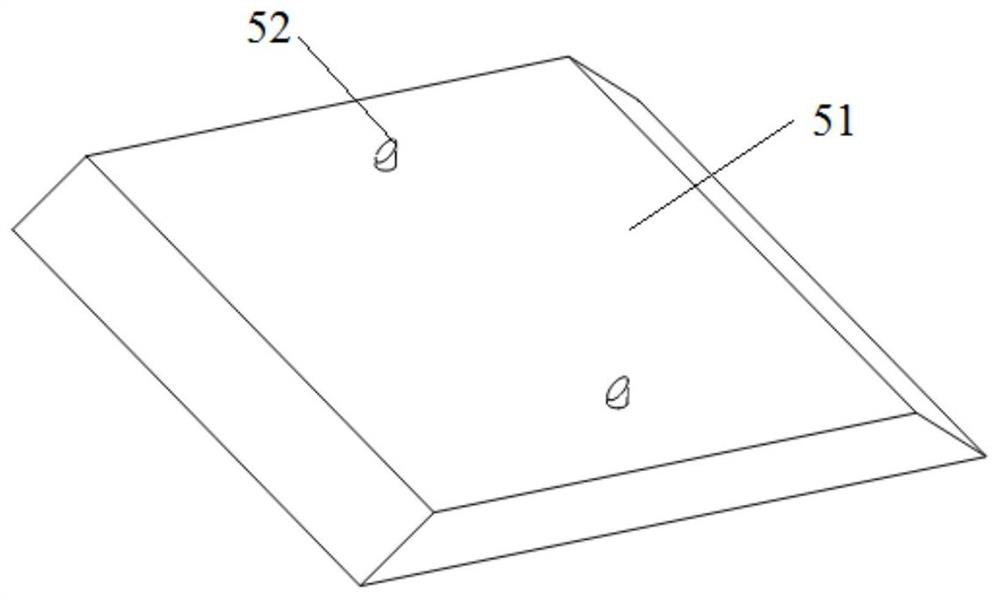
[0039] The main structure of this embodiment is the same as that in Embodiment 1, except that the specific size design of the positioning column 52 is provided with an inclined upward slope 53 along the moving direction of the product conveying material belt 7 on the positioning column 52. The angle of inclination of the inclined plane 53 is 60°. In order to facilitate the smooth movement of the product conveyor belt 7 under the action of the winding shaft 2, the positioning post 52 can be smoothly released from the positioning hole 71, and the bottom of the inclined plane 53 of the positioning post 52 is separated from the base The upper surface distance is 1mm, and the distance between the top of the slope 53 of the positioning column 52 and the upper surface of the base is 4mm.
PUM
 Abstract
Description
Claims
Application Information
 - R&D Engineer
- R&D Manager
- IP Professional
- Industry Leading Data Capabilities
- Powerful AI technology
- Patent DNA Extraction
Browse by: Latest US Patents, China's latest patents, Technical Efficacy Thesaurus, Application Domain, Technology Topic, Popular Technical Reports.
© 2024 PatSnap. All rights reserved.Legal|Privacy policy|Modern Slavery Act Transparency Statement|Sitemap|About US| Contact US: help@patsnap.com