Method for die-cutting foam

A foam and die-cutting technology, which is applied in metal processing and other directions, can solve the problems of weak adhesion between the protective film glue and the release film, unqualified products, and affecting subsequent processes, so as to avoid the separation and arching of the protective film and foam , Improve the effect of not easy to discharge waste and ensure the processing quality

Active Publication Date: 2020-12-29
上海昊佰智造精密电子股份有限公司
View PDF6 Cites 5 Cited by
  • Summary
  • Abstract
  • Description
  • Claims
  • Application Information

AI Technical Summary

Problems solved by technology

At present, the problems of this process are as follows: the waste of the foam inner frame is attached to the release film in the first step, and the waste is discharged by the protective film. The adhesive of the protective film and the release film are not strong, which makes it difficult to discharge the foam waste. , not easy to discharge, affecting the follow-up process; and during the second punching, the knife is punched from the surface of the protective film, because the foam has an internal hollow structure, the protective film on the foam is easy to be squeezed and wrinkled by the knife die; the waste of foam Difficulty in discharging and extrusion and wrinkling of the protective film will further cause the waste of the inner frame of the foam to be displaced due to waste discharge, resulting in unqualified product size or high size error; After the film, the weak adhesion between the foam and the protective film will also cause the protective film to arch, resulting in unqualified products
The unqualified rate of products processed by the current process is too high, which cannot meet the production demand

Method used


Image

  • Method for die-cutting foam
  • Method for die-cutting foam
  • Method for die-cutting foam

Examples


Embodiment

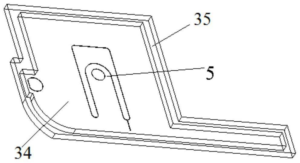
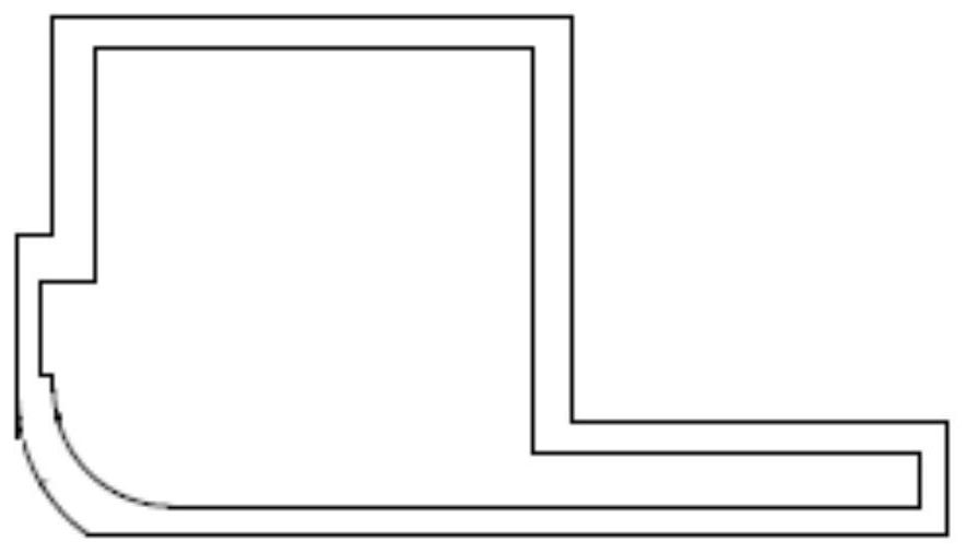
[0039] The product that the die-cutting method of present embodiment produces is as figure 1 and figure 2 As shown, this product is made up of protective film 34 and product main material 35, and product main material 35 is glue and foam. The foam is a frame-like structure hollowed out in the middle, including an inner frame and an outer frame. The size of the outer frame is greater than that of the inner frame, and the distance between the outer frame and the inner frame is 1 mm. The protective film 31 is provided with a protective film handle 5 .

[0040] The method for die-cutting foam of the present embodiment may further comprise the steps:

[0041] one die cut

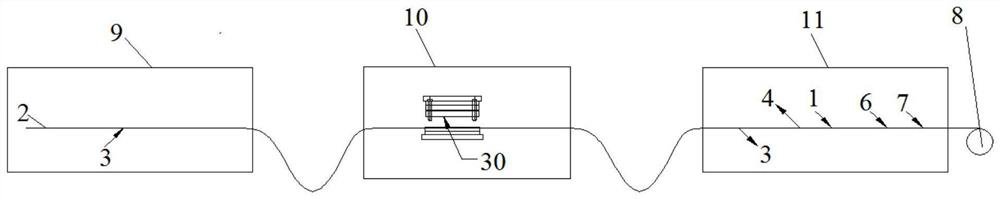
[0042] This step is in order to process the surface structure of the protective film on the product, and punch out structures such as the protective film handle 5 and the positioning hole on the protective film; the specific method is as follows: image 3 As shown, the first winding roller 8 is used to drive...


PUM


Abstract

The invention relates to a method for die-cutting foam. The method comprises the following steps that a first protective film is attached to a second protective film; the second protective film is primarily punched; the second protective film is attached to protective film waste after primary punching to be separated from the second protective film; then the foam, double faced adhesive tape and afirst release film are sequentially attached to the second protective film; an inner frame is obtained through secondary punching on the first release film and the foam, and the first release film onthe surface of the inner frame and the inner frame waste obtained after secondary punching are removed; the first release film on an intermediate product is completely removed, a complete second release film is attached to the surface of the foam, an outer frame is obtained through tertiary punching on the second release film, the foam and the second protective film, all waste on the appearance ofthe product is removed, and the second release film on the product is removed; and the outer frame is larger than the inner frame in size. Compared with the prior art, the method has the advantages of high processing precision, no product deformation, no arching of the protective films and the like.

Description

technical field [0001] The invention relates to the technical field of die-cutting, in particular to a method for die-cutting foam. Background technique [0002] For electronic products, a large amount of cushioning materials will be used in the application process. These cushioning materials are mostly foamed foam (referred to as: foam) in the die-cutting industry. Due to differences in assembly methods and product shapes, this As a result, the proportion of abnormalities in the die-cutting process is as high as 30%. The existing die-cutting process is divided into two times of punching. First, the protective film is pasted on the non-leaving surface of the release film, and then glue and foam are pasted on the release surface. The sticky pull-down of the protective film removes the foam waste in the inner frame, and then sticks the protective film on the front and back of the release film; then punches out the shape of the outer frame and the inside of the product twice, ...

Claims


Application Information

Patent Timeline
Patent Type & Authority Applications(China)
IPC IPC(8): B26F1/40B26F1/44B26D7/27B29C63/02
CPCB26F1/40B26F1/44B26D7/27B29C63/02
Inventor 蒋建国刘晓鹏
Owner 上海昊佰智造精密电子股份有限公司
Why Eureka
Try Eureka