Thin-wall section steel floor slab layer

A thin-walled section steel and floor slab technology, which is applied to floors, building components, buildings, etc., can solve the problems of complex process and difficult construction, and achieve the effect of speeding up the construction progress and reducing the difficulty of construction

Pending Publication Date: 2020-12-29
茅金声
View PDF0 Cites 0 Cited by
  • Summary
  • Abstract
  • Description
  • Claims
  • Application Information

AI Technical Summary

Problems solved by technology

However, the process is complicated and the construction is difficult

Method used


Image

  • Thin-wall section steel floor slab layer
  • Thin-wall section steel floor slab layer
  • Thin-wall section steel floor slab layer

Examples


Embodiment Construction

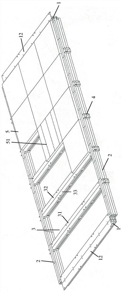
[0027] figure 1 A basic thin-walled steel floor slab layer according to the present invention is shown, and a plurality of basic thin-walled shaped steel floor slab layers can be spliced ​​together to form a floor slab layer as required.

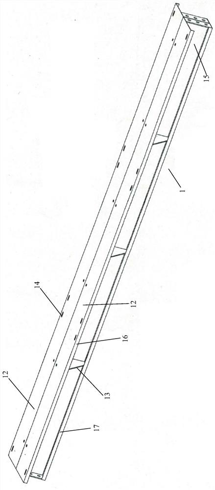
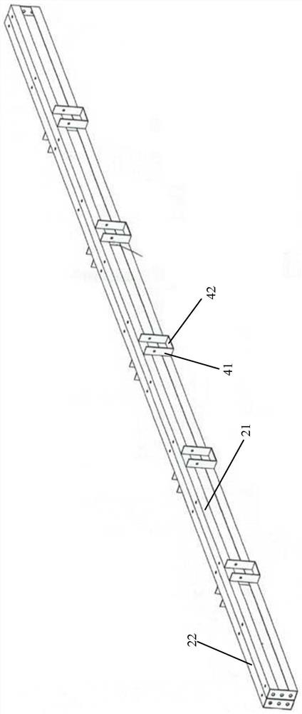
[0028] figure 1 The basic thin-walled steel floor slab layer showing the present invention comprises: a pair of parallel support beams 2, namely located in figure 1 The upper upper support beam 2 and the figure 1 The lower support beam 2 at the lower part; a pair of end support beams 1 arranged at both ends of the pair of parallel support beams 2, namely located in the figure 1 The left end support beam 1 on the left and is located at figure 1 The right end support beam 1 on the right side, the upper support beam 2, the lower support beam 2, the left end support beam 1 and the right end support beam 1 of the present invention constitute the ring beam of the floor layer of the present invention, which is used as a support beam for the floo...


PUM


Abstract

The invention discloses a thin-wall section steel floor slab layer. The thin-wall section steel floor slab layer comprises a pair of parallel supporting beams, a pair of end supporting beams, multiplefloor slab mounting strips and multiple rectangular floor slabs. The pair of end supporting beams is arranged at the two ends of the pair of parallel supporting beams, and the pair of supporting beams and the end supporting beams form a ring beam of the floor slab layer. The multiple floor slab mounting strips are mounted between the pair of supporting beams. The multiple rectangular floor slabsare mounted on the multiple floor slab mounting strips. By means of the thin-wall section steel floor slab layer, the construction progress of the floor slab layer can be accelerated.

Description

technical field [0001] The invention relates to the technical field of house construction, in particular to a thin-walled steel floor slab that can be rapidly constructed. Background technique [0002] The existing floor slab is made of natural fiber and quartz sand through pulping, molding, cutting, pressing and curing, and has the functions of waterproof, anti-corrosion and fire prevention. However, the process is complex and the construction is difficult. [0003] Therefore, there is a need to develop a floor slab that is easy to construct and can speed up the construction progress. SUMMARY OF THE INVENTION [0004] The purpose of the present invention is to provide a thin-walled steel floor layer that can speed up the construction progress. By prefabricating various construction components and assembling them on the construction site, the floor layer construction can be quickly completed. [0005] The thin-walled steel floor slab layer of the present invention compri...

Claims


Application Information

Patent Timeline
Patent Type & Authority Applications(China)
IPC IPC(8): E04B5/14E04C2/292E04C2/30E04C2/38
CPCE04B5/14E04C2/292E04C2/30E04C2/384
Inventor 茅金声林小彬童惠萍
Owner 茅金声
Why Eureka
Try Eureka