Eureka AIR delivers breakthrough ideas for toughest innovation challenges, trusted by R&D personnel around the world.

Plasma gasification ignition device of coal-fired boiler

A coal-fired boiler and ignition device technology, which is applied in the direction of combustion ignition, combustion method, lighting and heating equipment, etc., can solve the problems of non-concentrated flame drifting, and the ignition device cannot fully burn coal powder, etc., to achieve high-efficiency combustion and high flame temperature Effect

Pending Publication Date: 2020-12-29
华能安源发电有限责任公司
View PDF0 Cites 0 Cited by
  • Summary
  • Abstract
  • Description
  • Claims
  • Application Information

AI Technical Summary

Problems solved by technology

[0004] The purpose of the present invention is to provide a plasma gasification ignition device for a coal-fired boiler, to solve the above-mentioned background technology. Inadequacies, for example, when the quality of pulverized coal in the boiler is poor, the ignition device cannot fully burn the pulverized coal, and at the same time, the ignition device will also have the problem that the flame is not concentrated when burning the pulverized coal

Method used


Image

  • Plasma gasification ignition device of coal-fired boiler
  • Plasma gasification ignition device of coal-fired boiler
  • Plasma gasification ignition device of coal-fired boiler

Examples


Embodiment Construction

[0018] The following will clearly and completely describe the technical solutions in the embodiments of the present invention with reference to the accompanying drawings in the embodiments of the present invention. Obviously, the described embodiments are only some, not all, embodiments of the present invention. Based on the embodiments of the present invention, all other embodiments obtained by persons of ordinary skill in the art without making creative efforts belong to the protection scope of the present invention.

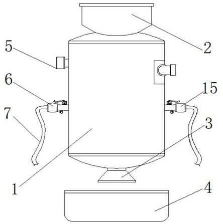
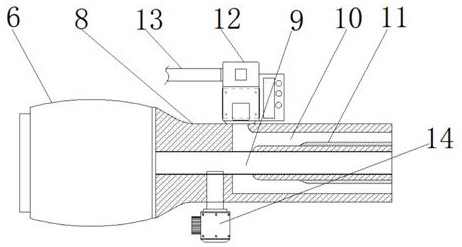
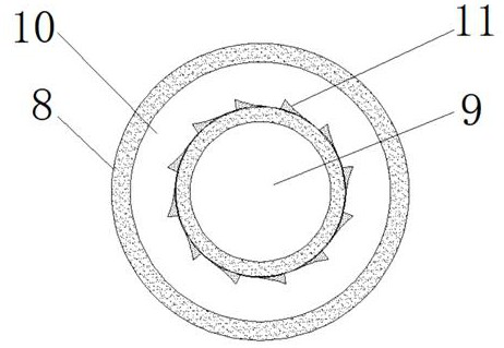
[0019] see Figure 1-3 , the present invention provides a technical solution: a plasma gasification ignition device for a coal-fired boiler, including a boiler body 1, a feeding device 2, a waste discharge hole 3, a cinder collection box 4, an air inlet 5, and a No. 1 plasma combustion Device 6, intake hose 7, flame nozzle 8, air passage 9, air passage 10, spiral vortex bar 11, solenoid valve 12, air intake pipe 13, igniter 14, No. 2 plasma combustion device 1...


PUM


Abstract

The invention discloses a plasma gasification ignition device of a coal-fired boiler. The plasma gasification ignition device comprises a boiler body and an air duct, a feeding device is arranged at the upper end of the boiler body, a waste discharging hole is formed in the lower end of the boiler body, a coal slag collecting box is arranged at the lower end of the waste discharging hole, an air inlet is formed in one side of the upper end of the boiler body, a first plasma combustion device is arranged below the air inlet, a second plasma combustion device is arranged on one side of the middle of the boiler body, and air inlet hoses are arranged on the outer side of the first plasma combustion device and the outer side of the second plasma combustion device. The plasma gasification ignition device is provided with the air duct, the air duct communicates with an air inlet pipe through an electromagnetic valve, the electromagnetic valve is used for guiding the air into the air duct through the air inlet pipe, the flow speed of the air is adjusted under control of the electromagnetic valve, and the air duct is mainly used for accelerating flames output by a flaming pipe nozzle.

Description

technical field [0001] The invention relates to the technical field of plasma ignition devices for coal-fired boilers, in particular to a plasma gasification ignition device for coal-fired boilers. Background technique [0002] Plasma combustion technology refers to the combustion technology that uses direct current air plasma as the ignition source to realize the oil-free ignition without a drop of oil for the cold start of the boiler. Plasma has the characteristics of promoting combustion. The plasma combustion system mainly includes combustion system, air powder system, plasma generator, electrical system, plasma air system and plasma cooling water system. [0003] At present, most of the plasma ignition devices for coal-fired boilers commonly used in the market are similar, but some shortcomings have also been found in the actual use process. At the same time, when the ignition device burns the coal powder, the flame will not be concentrated. Therefore, we propose a pla...

Claims


Application Information

Patent Timeline
IPC IPC(8): F23Q13/02
CPCF23Q13/02
Inventor 廖勇黄志勇邹仁吴欣彭飞彭饶飞孔庆浩杜建鑫李春明姚翼虎
Owner 华能安源发电有限责任公司
Why Eureka
Eureka Blog
Learn More