Automatic locking vibration damper
A technology of automatic locking and anti-vibration hammer, applied in the direction of mechanical vibration damping device, etc., can solve the problems of consuming the physical strength of the staff, sliding, reducing the anti-vibration effect, etc., to improve the practicability and applicability, and the operation is fast, efficient and convenient. The effect of quick disassembly
- Summary
- Abstract
- Description
- Claims
- Application Information
AI Technical Summary
Problems solved by technology
Method used
Image

Examples
Embodiment 1
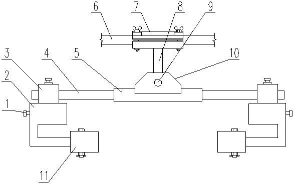
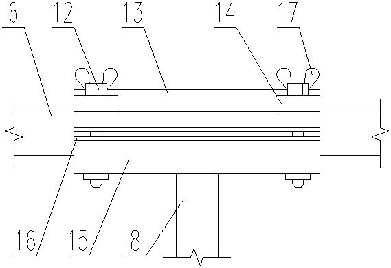
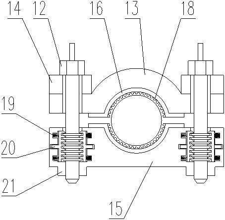
[0022] like Figure 1-6 As shown, the automatic locking anti-vibration hammer includes a main hammer head 2 and a connecting rod 4, both ends of the connecting rod 4 are slidably connected to a connecting jack block 3, and the connecting jack block 3 is rotatably connected to a main hammer Head 2, the main hammer head 2 is connected with an adjustment counterweight 11; the inside of the connecting top block 3 is provided with a cavity, the bottom of the cavity is arc-shaped, and a compression arc plate is arranged in the cavity 28, the top of the compression arc plate 28 is rotatably connected with a compression bolt 29, and the compression bolt 29 passes through the top of the connection top block 3 and is threadedly connected with the connection top block 3; the middle part of the connection rod 4 A connection sleeve 5 is connected, the top of the connection sleeve 5 is connected with an intermediate block 10, the top of the intermediate block 10 is connected with an interme...
Embodiment 2
[0025] like Figure 1-6 As shown, the automatic locking anti-vibration hammer includes a main hammer head 2 and a connecting rod 4, both ends of the connecting rod 4 are slidably connected to a connecting jack block 3, and the connecting jack block 3 is rotatably connected to a main hammer Head 2, the main hammer head 2 is connected with an adjustment counterweight 11; the inside of the connecting top block 3 is provided with a cavity, the bottom of the cavity is arc-shaped, and a compression arc plate is arranged in the cavity 28, the top of the compression arc plate 28 is rotatably connected with a compression bolt 29, and the compression bolt 29 passes through the top of the connection top block 3 and is threadedly connected with the connection top block 3; the middle part of the connection rod 4 A connection sleeve 5 is connected, the top of the connection sleeve 5 is connected with an intermediate block 10, the top of the intermediate block 10 is connected with an intermedi...
PUM
 Abstract
Description
Claims
Application Information
 - R&D
- Intellectual Property
- Life Sciences
- Materials
- Tech Scout
- Unparalleled Data Quality
- Higher Quality Content
- 60% Fewer Hallucinations
Browse by: Latest US Patents, China's latest patents, Technical Efficacy Thesaurus, Application Domain, Technology Topic, Popular Technical Reports.
© 2025 PatSnap. All rights reserved.Legal|Privacy policy|Modern Slavery Act Transparency Statement|Sitemap|About US| Contact US: help@patsnap.com