Rotor tooth crack inspection method

A technology of crack inspection and rotor teeth, which is applied to rotating parts of magnetic circuit, manufacturing stator/rotor body, using sonic/ultrasonic/infrasonic waves to analyze solids, etc. The effect of easy and reliable checking

Active Publication Date: 2020-12-29
MITSUBISHI ELECTRIC CORP
View PDF12 Cites 2 Cited by
  • Summary
  • Abstract
  • Description
  • Claims
  • Application Information

AI Technical Summary

Problems solved by technology

Therefore, a large-scale operation such as pulling out the rotor from the stator has to be carried out in conjunction with the periodic inspection, and other process operations are also required, so the penetration flaw detection test requires a lot of labor and time.

Method used


Image

  • Rotor tooth crack inspection method
  • Rotor tooth crack inspection method
  • Rotor tooth crack inspection method

Examples


Embodiment approach 1

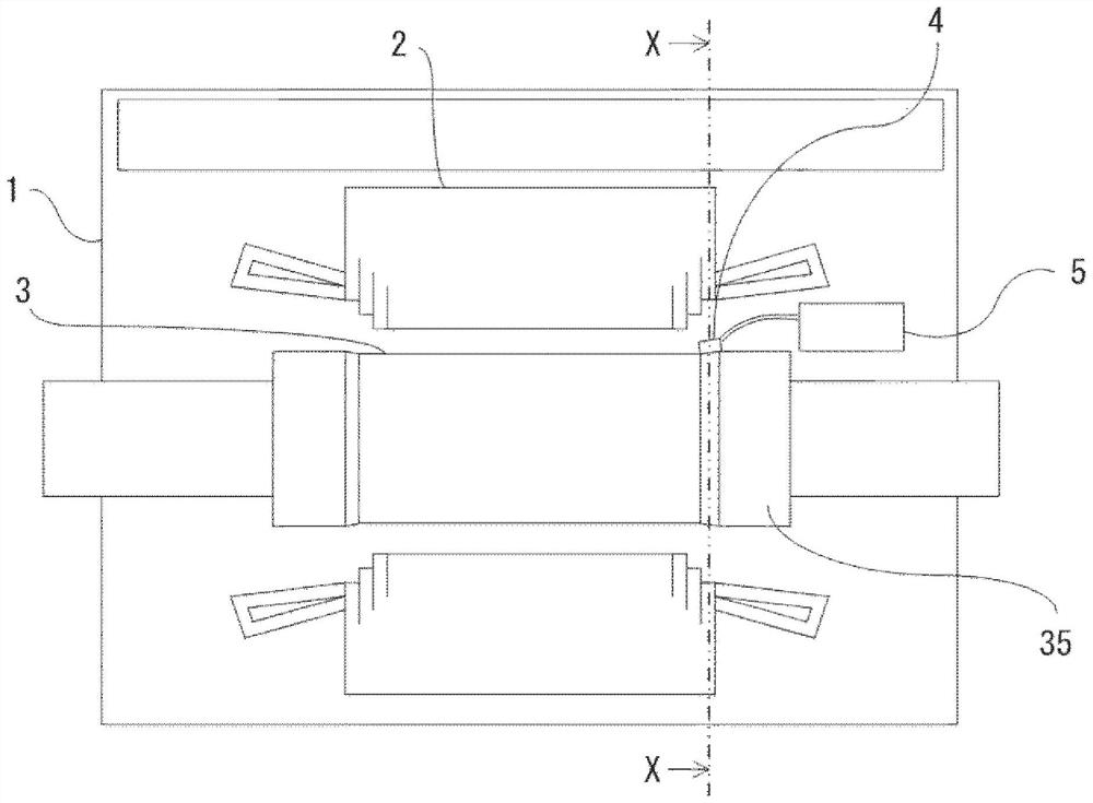
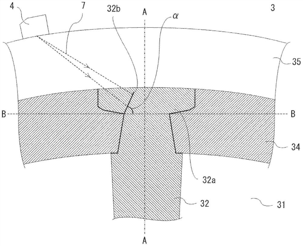
[0027]figure 1 It is a plan view showing a schematic structure of a turbine generator to which the rotor tooth crack inspection method of Embodiment 1 of the present application is applied,figure 2 Is alongfigure 1 A partial cross-sectional view of the X-X line.

[0028]In the turbine generator, the rotor 3 is rotatably provided inside the stator 2 supported by the frame 1. In the rotor 3, a plurality of slots 31 are formed radially in the radial direction along the circumferential direction of the armature core, and teeth 32 are formed between the slots 31, and an excitation coil for generating a magnetic field, not shown, is wound around each tooth. The state of the portion 32 is housed in the groove 31.

[0029]In addition, the excitation coil is stacked in the above-mentioned slot 31, but a wedge-shaped slot wedge 34 is inserted into the slot formed by the tooth shoulder 32a so that the excitation coil will not be removed from the slot due to the centrifugal force generated by the rot...


PUM


Abstract

When [alpha] defines an angle at which a crack (32b) develops with respect to a reference line (B) that orthogonally intersects a radial direction of a tooth (32) and a tooth shoulder (32a), a phasedarray probe (4) is preliminarily installed at a position on an outer circumferential surface of a retaining ring (35) in a direction that is estimated to be orthogonal to the crack development angle [alpha], and then a sector scan of an ultrasonic beam emitted from the phased array probe (4) is carried out so as to check whether or not there is a crack (32b) in the tooth shoulder (32a).

Description

Technical field[0001]The present application relates to a rotor tooth crack inspection method, which uses ultrasonic waves to check whether a crack is generated due to the stress generated at the shoulder of the tooth portion constituting the rotor of the rotating electric machine.Background technique[0002]As a rotating electric machine, for example, in the rotor of a turbine generator, a plurality of slots are formed radially along the circumferential direction of the armature core, and teeth are formed between the slots, and an excitation coil for generating a magnetic field is wound It is stored in the groove in the state of each tooth.[0003]As a result, the excitation coil is stacked and arranged in the slot, but a wedge-shaped slot wedge is inserted into the slot formed by the shoulder of the tooth so that the excitation coil does not fly out of the slot due to the centrifugal force generated by the rotation of the rotor. external. As a result, the slot wedge holds the excitati...

Claims


Application Information

Patent Timeline
Patent Type & Authority Applications(China)
IPC IPC(8): G01N29/04G01N29/26
CPCG01N29/26G01N2291/2693G01N29/262G01N29/043H02K15/02G01N2291/106G01N29/069G01N29/07G01N29/041H02K1/26
Inventor 大宅贵志内村政宪
Owner MITSUBISHI ELECTRIC CORP
Why Eureka
Try Eureka