
Three-dimensional auxiliary puncture positioning frame for lower brain nidi and positioning method thereof

A positioning frame and lesion technology, applied in the field of medical equipment, can solve the problems of reducing and shortening the operation preparation time, and achieve the effect of safe and accurate puncture

Pending Publication Date: 2021-01-01
杨利民
View PDF1 Cites 0 Cited by
  • Summary
  • Abstract
  • Description
  • Claims
  • Application Information

AI Technical Summary

Problems solved by technology

[0013] Aiming at the reality that the existing 3D printing guide plate positioning technology has a large investment in equipment and a certain amount of time for design and printing, the present invention provides a three-dimensional assisted puncture positioning frame for brain lesions and its positioning method. Precise positioning by the two-point-one-line positioning method eliminates the cumbersome process of designing and printing 3D guide plates and sterilizing 3D guide plates, greatly shortening the preparation time for surgery. This invention can reduce equipment investment and eliminate the need for guide plate design in the prior art, 3D printing printing and disinfection process, process, compression of operation preparation time, accurate positioning and orientation, implementation of immediate rescue operation, reducing functional loss of patients, saving patients' lives

Method used


Image

  • Three-dimensional auxiliary puncture positioning frame for lower brain nidi and positioning method thereof
  • Three-dimensional auxiliary puncture positioning frame for lower brain nidi and positioning method thereof
  • Three-dimensional auxiliary puncture positioning frame for lower brain nidi and positioning method thereof

Examples


Embodiment Construction

[0055] The technical solution of the present invention will be described in detail below with reference to the accompanying drawings. During the positioning process, the instrument of the present invention and related accessories need to be disinfected according to relevant regulations before they can be used in the positioning and puncturing of brain surgery.

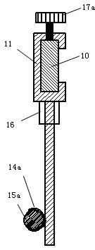
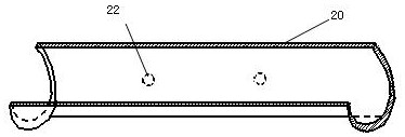
[0056] The technical solution of the present invention is a three-dimensional assisted puncture positioning frame for brain lesions, figure 1 It is a schematic diagram of the front structure of the puncture positioning frame of the present invention, figure 2 is along figure 1 Schematic cross-sectional view along A-A1 direction. Described puncture positioning frame comprises sliding ruler 10, and one end on sliding ruler 10 is provided with handle 13, and the opposite end of handle 13 on sliding ruler 10 is provided with the fixed card 12 that is connected with sliding ruler 10 on the vertical direction of sliding...


PUM

PropertyMeasurementUnit
Lengthaaaaaaaaaa

Abstract

The invention discloses a three-dimensional auxiliary puncture positioning frame for lower brain nidi and a positioning method thereof and belong to the field of medical instruments. The positioning frame comprises a sliding ruler, a handle is arranged at one end of the sliding ruler, a fixed clamp perpendicular to the sliding ruler is integrally arranged at the opposite end of the sliding ruler,a sliding clamp is slidably arranged on the opposite side of the fixed clamp on the sliding ruler, puncture positioning fixing pieces with opposite axes are arranged at the ends of the fixed clamp andthe sliding clamp respectively, the puncture positioning fixing pieces on the fixed clamp and the sliding clamp are arc-shaped grooves, a positioning needle is arranged in the arc-shaped groove in the fixed clamp in a matched mode, a positioning ruler and an adapter are arranged in the arc-shaped groove in the sliding clamp in a matched mode, and a center positioning opening and a plurality of auxiliary positioning holes are formed in the positioning ruler. According to the puncture positioning frame, equipment investment can be reduced, a guide plate is prevented from being printed, the operation preparation time can be shortened, after accurate positioning and orientation, a rescue operation is conducted in time, function loss of a patient can be reduced, and the life of the patient issaved.

Description

technical field [0001] The invention relates to a positioning frame, in particular to a three-dimensional assisted puncture positioning frame for lower brain lesions and a positioning method thereof, belonging to the field of medical devices. Background technique [0002] Brain lesions are common clinical diseases. Mild cases can cause dizziness, nausea, insomnia, memory loss, dementia, depression, moderate cases can cause aphasia, limbs remain unchanged, severe cases can cause bedridden paralysis, loss of consciousness, Become a vegetable, and even lead to death. [0003] In particular, cerebral hemorrhage caused by long-term high blood pressure is often an emergency, and it is necessary to implement aspiration and drainage of intracranial hematoma in a short period of time for rescue treatment, otherwise it will cause aggravation of the condition and even death. The treatment of cerebral hemorrhage is a life-and-death struggle against the god of death, and time is life in...

Claims


Application Information

Patent Timeline
IPC IPC(8): A61B17/34A61B34/10A61B90/00
CPCA61B17/3403A61B2017/3405A61B34/10A61B90/39A61B2034/107A61B2034/108A61B2090/3904A61B2090/3937
Inventor 杨利民范海霞杨舒雯何源索治国康朋
Owner 杨利民
Learn More