Assembly Method of Inner and Outer Arc Frames of Slab Continuous Casting Sectors

A technology of slab continuous casting and outer arc frame, which is applied to the assembly of outer arc frame and the sector of slab continuous casting, can solve the problems of low welding process efficiency, long welding cycle, long working hours, etc., so as to improve welding work efficiency , Improve the precision of pre-welding assembly and simplify the effect of manual operation

Active Publication Date: 2022-04-08
CHANGZHOU BAOLING HEAVY IND MACHINERY
View PDF0 Cites 0 Cited by
  • Summary
  • Abstract
  • Description
  • Claims
  • Application Information

AI Technical Summary

Problems solved by technology

[0004] 1. Head frame welding, main board and head welding, seat block welding, seat block butt welding need to be carried out step by step, and the welding cycle is longer;
[0005] 2. Due to the large number of blocks and the distribution on different main boards, when welding the block and the main board, it needs to be turned over and welded many times, and the welding space is narrow, so the working hours are long, the welding process efficiency is low, and the welding process is difficult. Seam quality is not easy to guarantee;
[0006] 3. Since the processing of the surfacing surface on the seat block is carried out after the assembly and welding of the sector frame is completed, the machining of the surfacing surface on the seat block needs to be carried out on a large machine tool, which is time-consuming and costly;
[0007] 4. Due to the large volume of the main board and the head frame after welding, in the prior art, the surfacing welding on the block is carried out manually, and the surfacing welding efficiency is low and the quality is not stable.

Method used


Image

  • Assembly Method of Inner and Outer Arc Frames of Slab Continuous Casting Sectors
  • Assembly Method of Inner and Outer Arc Frames of Slab Continuous Casting Sectors
  • Assembly Method of Inner and Outer Arc Frames of Slab Continuous Casting Sectors

Examples


Embodiment Construction

[0030] Combine below Figure 1 to Figure 9 The present invention will be described in detail.

[0031] The method for assembling the inner and outer arc frames of the slab continuous casting segment of the present invention comprises the following steps:

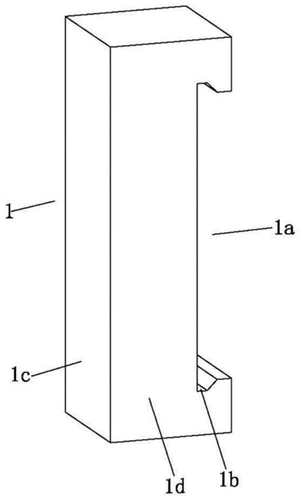
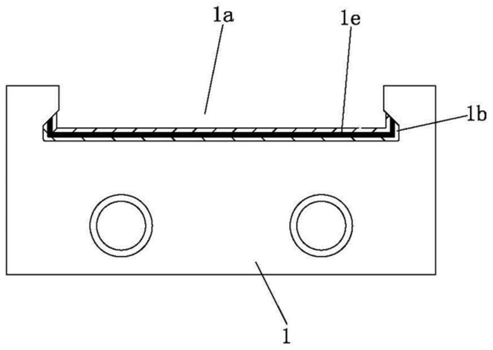
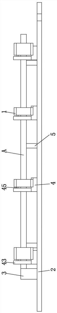
[0032] Step 1, machine the surfacing welding parts on the block 1, and use a robot to surfacing welding the block 1 in batches. Wherein the surfacing welding part is the groove 1a processed on the block 1, between the groove wall surface of the groove 1a and the bottom of the groove, there is a concave limit 1b recessed to the outside of the seat block 1, and the depth of the concave limit 1b is 3.2-4mm, the depth of the concave limit 1b is preferably 3.5mm, the height of the concave limit 1b is 6.5-7.5mm, and the height of the concave limit 1b is preferably 7mm. For surfacing welding from the groove bottom of the groove 1a, the surfacing welding wire is preferably made of ferritic stainless steel. The surfacing layer 1e ...


PUM

PropertyMeasurementUnit
depthaaaaaaaaaa
heightaaaaaaaaaa

Abstract

The invention discloses a method for assembling the inner and outer arc frames of the slab continuous casting sector, step 1, using a robot to weld the seat block in batches; step 2, according to the position of the limiting part and the actual welding of the seat block and the main board position, a plurality of second marks are set on the welding platform along the length direction of the main board, and the first positioning parts for positioning the seat block are fixed at each second mark, and are fixed on the welding platform for supporting the main board to make the main board and welding Form the first spacer between the platforms; step 3, put the main board on the first spacer, adjust the main board so that the wide side of the main board is against the limit part, and make the main board and the first positioning part and the seat block After reaching the top, weld the main board and the seat block; step 4, put the main board on the second positioning part, put the head frame on the second spacer, and weld the head frame and the main board. The invention has the advantages of simplifying the welding and assembling technological process, improving the assembling efficiency and improving the assembling precision before welding.

Description

technical field [0001] The invention relates to an assembly method of the inner and outer arc frames of the slab continuous casting segment. Background technique [0002] The slab segment frame is an important part of the continuous casting equipment. It is installed behind the mold of the continuous casting machine and is a key component of the continuous casting machine that supports and guides the slab during solidification. In the middle, the slab is cooled to assist in the forming of the slab. The whole set of fan section is divided into bending section, arc section, straightening section and horizontal section, and each fan section is divided into inner arc frame, outer arc frame and pinch roller frame. The structural characteristics of the inner and outer arc frames of the sector are: usually composed of 2 head frames with shaft heads and 6-8 main boards supported in the middle of the head frames. The main boards have specific angles, and each main board usually has ...

Claims


Application Information

Patent Timeline
Patent Type & Authority Patents(China)
IPC IPC(8): B23K31/02
CPCB23K31/02
Inventor 仇晨芮肯法邱焱周炜张佩
Owner CHANGZHOU BAOLING HEAVY IND MACHINERY
Why Eureka
Try Eureka