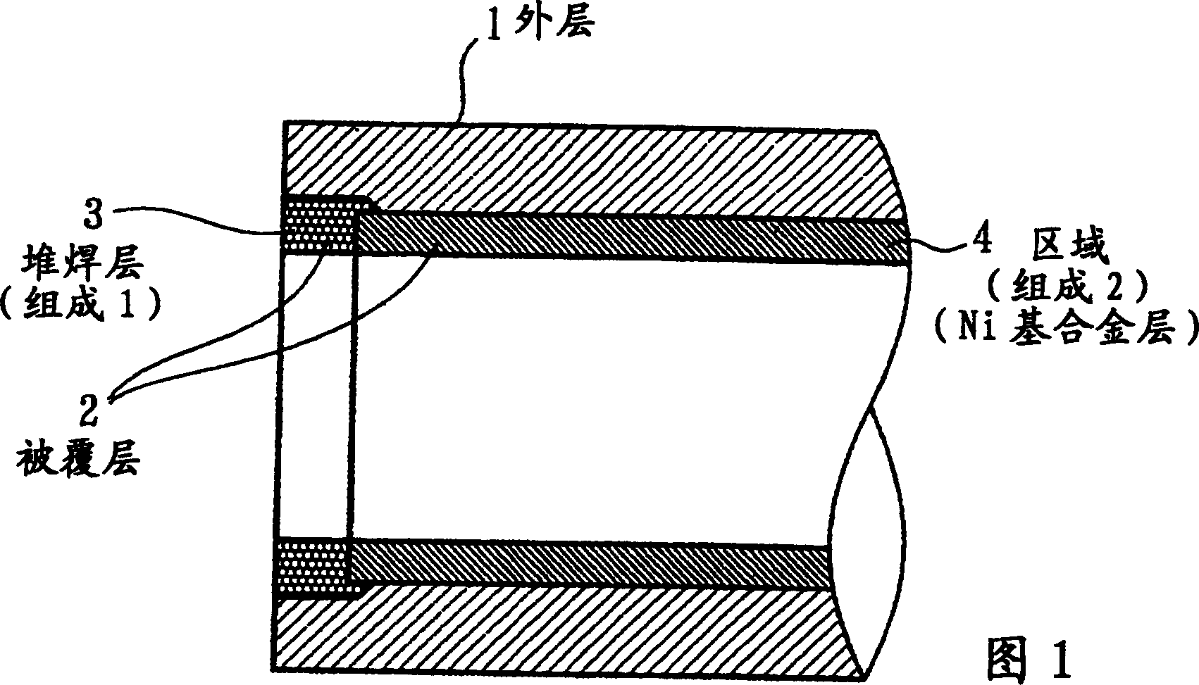
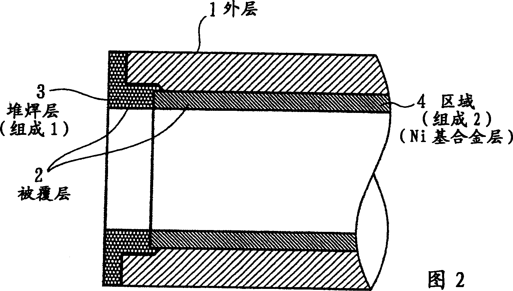
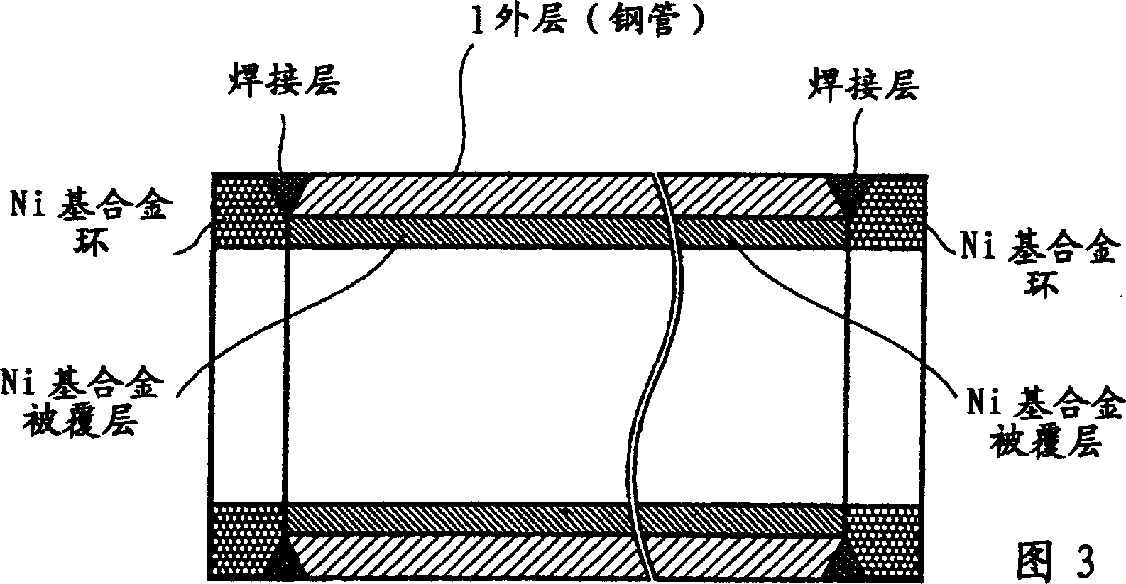
Clad pipe

A composite pipe and alloy steel pipe technology, applied in the structural field of composite pipes, can solve the problems of pipe bending, high cost, no clear boundary between the base material and the solder layer, etc., and achieves the effects of easy welding and excellent corrosion resistance.

Inactive Publication Date: 2006-06-07
DAI ICHI HIGH FREQUENCY
View PDF1 Cites 11 Cited by
  • Summary
  • Abstract
  • Description
  • Claims
  • Application Information

AI Technical Summary

Problems solved by technology

[0010] 1. Due to the surfacing welding on the inner surface of the long tube, the tube will bend
[0011] 2. Since a diluted layer of the base metal component and the solder (meat) component will be formed at the boundary between the base metal steel pipe and the solder layer (surfacing layer) during surfacing, in order to form a specified thickness of the surfacing layer with a specified composition, The thickness of the diluted layer must be overlayed
As a result, there is a disadvantage that the cost increases
[0012] 3. There is no clear boundary between the base metal and the solder layer due to the presence of a dilution layer
making the cost extremely high
[0015] 2. In addition, it is obvious that it is difficult to manufacture long-sized products

Method used


Image

  • Clad pipe
  • Clad pipe
  • Clad pipe

Examples


Embodiment 1

[0218] As the outer layer steel pipe, STKM13A carbon steel pipe for machine structure with the following specifications was used.

[0219] The chemical composition of STKM13A carbon steel pipe for mechanical construction is:

[0220] C: ≤0.20% Si: ≤0.35% Mn: ≤0.60%

[0221] P: ≤0.04% S: ≤0.04%.

[0222] The outer layer steel pipe was processed to have an outer diameter of 315mmφ, an inner diameter of 275mmφ, and a length of 2000mm.

[0223] Machine the inner end into Image 6 In that way, a Ni-based alloy equivalent to inconel 625 is surfacing. After surfacing, machining into Figure 7 That way (thickness of the solder layer: 6mm).

[0224] The tube was laid down horizontally, and the whole was induction-heated to 1050°C, and a molten liquid having the following composition was poured into the tube while rotating.

[0225] The chemical composition of the melt is:

[0226] Cr: 18% C: 0.8% B: 3.5%

[0227] Si: 4.0% the rest is Ni and impurities

[0228]The injection tem...

Embodiment 2

[0238] Corrosion Test 1 (Example of Alloy 1)

[0239] Ni-based alloys with different composition were left for 48 hours in a humidified hydrogen sulfide flowing atmosphere, and the weight change (increase) was investigated to conduct a comparative test of corrosion resistance.

[0240] Sample size: 20×20×5mm

[0241] Flow rate of hydrogen sulfide: 100ml / min

[0242] Time: 48 hours

[0243] Temperature: room temperature

[0244] Table 1 shows the composition of the Ni-based alloy (alloy 1) and the measurement results of the corrosion gain.

[0245] Table 1

[0246] serial number

Cr

B

Si

C

Fe, Co

Mo

Nb

Ni

weight change

Remark

1

15

3.2

4.4

0.7

Fe3.5

the remaining

5.210

2

18

3.5

4.0

0.3

Co3.0

16

the remaining

1.680

3

15

3.1

4.3

0.8

Fe3.5

the remaining

...

Embodiment 3

[0252] Corrosion Test 2 (Example of Alloy 2)

[0253] Ni-based alloys with different composition were left for 48 hours in a humidified hydrogen sulfide flowing atmosphere, and the weight change (increase) was investigated to conduct a comparative test of corrosion resistance.

[0254] Sample size: 20×20×5mm

[0255] Hydrogen sulfide flow rate: 100ml / min

[0256] Time: 48 hours

[0257] Temperature: room temperature

[0258] Table 2 shows the composition of the Ni-based alloy (alloy 2) and the measurement results of corrosion increment.

[0259] Table 2

[0260] serial number

B

Si

C

Fe, Co

Mo

Nb

Al

Cu

Cr

Ni

weight change

1

5.0

3.0

0.1

4

the remaining

1.02

2

3.0

6.0

0.1

the remaining

0.95

3

4.0

9.0

0.1

0.1

the remaining

0.97

4

2.5

...


PUM


Abstract

The present invention relates to the structure of a composite pipe with excellent corrosion resistance used for oil pipelines, oil well pipes, etc., and provides a structure in which the inner surface of the pipe is coated with a Ni-based alloy with excellent corrosion resistance. This composite pipe is a composite pipe in which the outer layer 1 is made of ordinary steel or low-alloy steel, and the coating layer 2 is made of Ni-based corrosion-resistant alloy. It is characterized in that the regions 3 at both ends of the inner layer 2 are outside The inner surface of the layer 1 is formed by overlay welding, and the region 4 other than the two ends is made to have a solidus temperature of 1300° C. or lower than the solidus temperature of the Ni-based alloy formed by the overlay welding. A Ni-based alloy with a composition lower than 150°C or higher is welded to the surfacing layer and the inner surface of the outer layer.

Description

technical field [0001] The present invention relates to the structure of a composite pipe excellent in corrosion resistance, and more specifically relates to a structure of a composite pipe mainly used in oil pipelines and oil well pipes where the inner surface of the pipe is coated with a Ni-based alloy excellent in corrosion resistance to hydrogen sulfide and the like. Background technique [0002] Oil and gas fields are buried in the ground with many corrosive components such as hydrogen sulfide, and are used for oil well pipes and pipelines for mining and transporting oil and natural gas (hereinafter referred to as "crude oil") containing such corrosive components, and for supplying Drilling pipes that are excavated with mud of the same corrosive composition (hereinafter collectively referred to as "oil well pipes"), especially on the inner surface of the pipe that is constantly renewed and in contact with the above-mentioned corrosive fluid, must have corrosion resistanc...

Claims


Application Information

Patent Timeline
IPC IPC(8): F16L9/02B22D19/00F16L58/08
Inventor 松原洋一竹屋昭宏宫田征一郎
Owner DAI ICHI HIGH FREQUENCY
Why Eureka
Try Eureka