New energy automobile tire damping device buffered through spring
A technology for new energy vehicles and shock absorbers, applied in springs/shock absorbers, vehicle springs, vehicle maintenance, etc., can solve problems such as low service life, and achieve the effects of high service life, safe driving, and increased service life.
- Summary
- Abstract
- Description
- Claims
- Application Information
AI Technical Summary
Problems solved by technology
Method used
Image
Examples
Embodiment 1
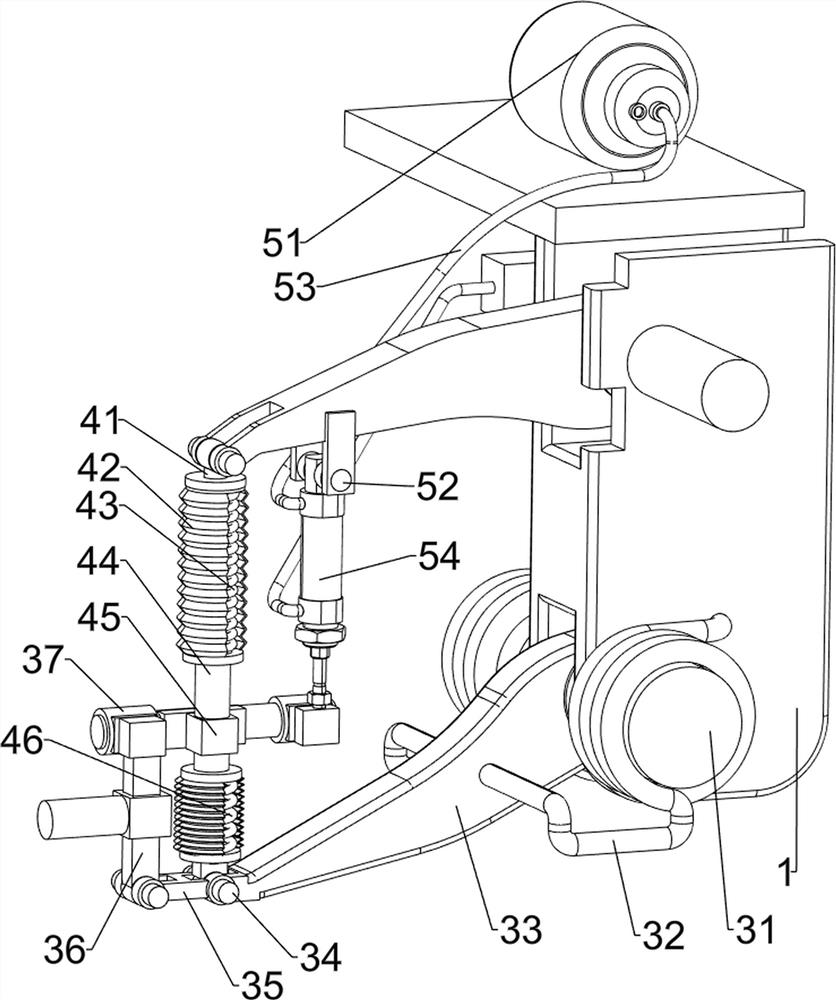
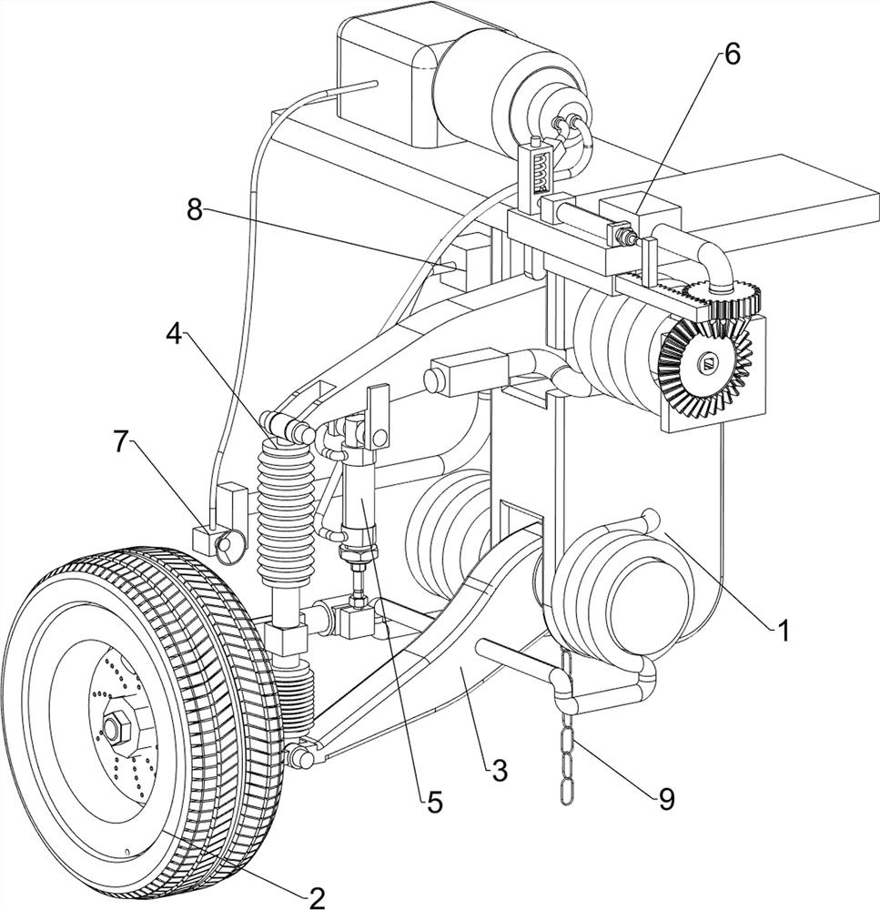
[0028] A new energy vehicle tire damping device buffered by a spring, such as figure 1 and figure 2 As shown, it includes a mounting frame 1, a tire 2, a balance mechanism 3, a shock absorbing mechanism 4 and a first adjustment mechanism 5. Tire 2, the upper left side of mounting frame 1 is rotatably provided with shock absorbing mechanism 4, and shock absorbing mechanism 4 is connected with balance mechanism 3, is provided with first adjusting mechanism 5 between shock absorbing mechanism 4 and mounting frame 1.
[0029] The balance mechanism 3 includes a first rotating shaft 31, a first torsion spring 32, a support rod 33, a second rotating shaft 34, a first connecting rod 35, a second connecting rod 36 and a third connecting rod 37, and the left side of the mounting frame 1 is symmetrical up and down. The rotary type is provided with a first rotating shaft 31, and the middle part of the first rotating shaft 31 is connected with a support rod 33, and a first torsion spring...
Embodiment 2
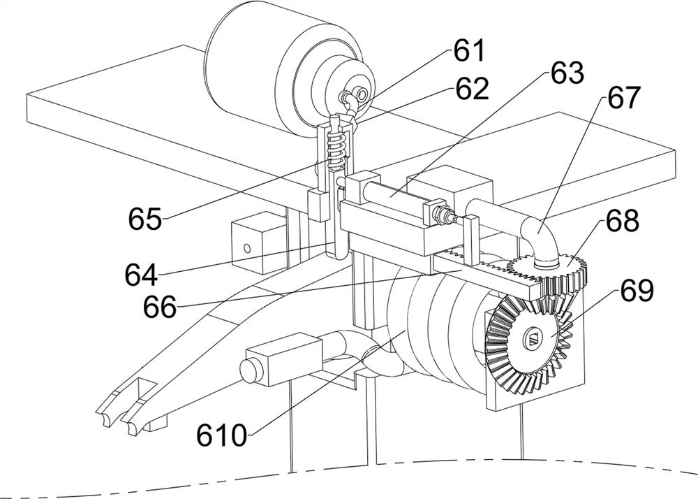
[0034] On the basis of Example 1, such as image 3 , Figure 4 and Figure 5 Shown, also include the second adjustment mechanism 6, the second adjustment mechanism 6 includes the second air guide pipe 61, the valve 62, the second cylinder 63, the clamp rod 64, the third spring 65, the rack 66, the connecting rod 67, The spur gear 68, the bevel gear set 69 and the second torsion spring 610, the second air guide pipe 61 is connected between the gas storage tank 51 and the left side of the installation frame 1, the middle part of the second air guide pipe 61 is equipped with a valve 62, and the top of the installation frame 1 The left front side is equipped with a second air cylinder 63, and the second air guide pipe 61 is connected with the second air cylinder 63. The sliding type on the left front side of the mounting frame 1 is provided with a clamp bar 64, and the clamp bar 64 cooperates with the support rod 33 on the upper side. The third spring 65 is connected between the...
PUM
 Abstract
Description
Claims
Application Information
 - R&D
- Intellectual Property
- Life Sciences
- Materials
- Tech Scout
- Unparalleled Data Quality
- Higher Quality Content
- 60% Fewer Hallucinations
Browse by: Latest US Patents, China's latest patents, Technical Efficacy Thesaurus, Application Domain, Technology Topic, Popular Technical Reports.
© 2025 PatSnap. All rights reserved.Legal|Privacy policy|Modern Slavery Act Transparency Statement|Sitemap|About US| Contact US: help@patsnap.com


