Device for automatically controlling pouring height and vibrating

A technology of pouring height and vibrating rod is applied in the field of building pouring, which can solve the problems of inconvenient walking, damage to the steel structure, and workers cannot well control the time, direction and depth of the vibration, so as to reduce the work Risk, the effect of improving pouring efficiency

Inactive Publication Date: 2021-01-01
绍兴多卡机械设备有限公司
View PDF0 Cites 0 Cited by
  • Summary
  • Abstract
  • Description
  • Claims
  • Application Information

AI Technical Summary

Problems solved by technology

[0002] At present, when pouring buildings, the direction of the mud pouring pipeline is usually controlled manually. First, it is inconvenient for people to walk on the steel bars. Secondly, the pouring pipeline is very heavy. When moving, three to four people are usually used to control the pouring, and the personnel do not It is impossible to accurately control the free fall height of the mud from the pipe mouth to the pouring surface according to the needs of the mud during pouring, resulting in uneven pouring quality. At present, manual vibration is used during construction, and workers cannot control it well. The time, direction and depth of vibration are easy to cause damage to the steel structure

Method used


Image

  • Device for automatically controlling pouring height and vibrating
  • Device for automatically controlling pouring height and vibrating
  • Device for automatically controlling pouring height and vibrating

Examples


Embodiment Construction

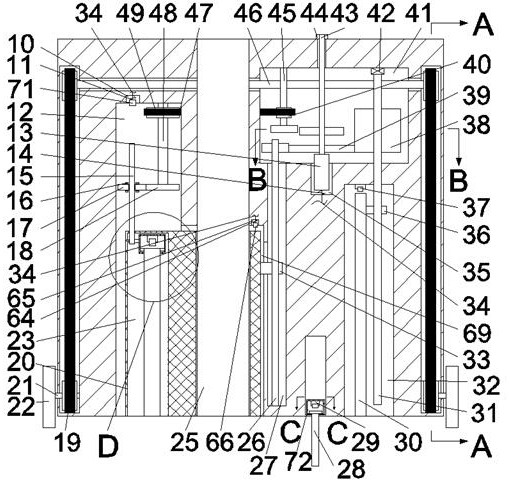
[0016] Combine below Figure 1-5 The present invention is described in detail, wherein, for the convenience of description, the orientations mentioned below are defined as follows: figure 1 The up, down, left, right, front and back directions of the projection relationship itself are the same.

[0017] A device for automatically controlling pouring height and vibration described in conjunction with accompanying drawings 1-5 includes a main box body 68, and the main box body 68 is provided with a pipe block chamber 69 with an opening downward, and the pipe block chamber 69 The upper end wall is fixedly connected with a pipeline cavity 25 extending upwards to communicate with the upper end wall of the main box 68 and extending downwards to communicate with the lower end of the main box 68. The main box 68 is located in the pipeline. The left side of the block cavity 69 is communicated with a second pulley cavity 12 with an opening downward, and the upper side of the second pull...


PUM


Abstract

The invention relates to the related field of building pouring, and discloses a device for automatically controlling the pouring height and vibrating. The device comprises a main box body, wherein themain box body is provided with a pipeline block cavity with a downward opening, and a pipeline cavity which extends upwards to communicate with the upper end wall of the main box body and extends downwards to communicate with the lower end face of the main box body is fixedly connected in the upper end wall of the pipeline block cavity. According to the device, through meshing of a fourth gear and a sixth gear, the optimal pouring height can be adjusted according to the specific mud strength, and standardized operation of pouring construction is ensured; meanwhile, through up-down moving of avibrating rod, the vibrating work of mud is completed, the vibrating time and depth can be ensured, and a steel bar structure is not damaged while vibrating is conducted; and the device is connectedwith a mud pouring vehicle, manual positioning and moving work is not needed, the working risk is reduced, and the pouring efficiency can be better improved.

Description

technical field [0001] The invention relates to the field of building pouring, in particular to a device for automatically controlling the pouring height and vibrating. Background technique [0002] At present, when pouring buildings, the direction of the mud pouring pipeline is usually controlled manually. First, it is inconvenient for people to walk on the steel bars. Secondly, the pouring pipeline is very heavy. When moving, three to four people are usually used to control the pouring, and the personnel do not It is not possible to accurately control the free fall height of the mud from the pipe mouth to the pouring surface according to the needs of the mud during pouring, resulting in uneven pouring quality. At present, manual vibration is used during construction, and workers cannot control it well. The time, direction and depth of vibration are easy to cause damage to the steel structure. Contents of the invention [0003] The object of the present invention is to p...

Claims


Application Information

Patent Timeline
Patent Type & Authority Applications(China)
IPC IPC(8): E04G21/04E04G21/08
CPCE04G21/0418E04G21/08
Inventor 付会若
Owner 绍兴多卡机械设备有限公司
Why Eureka
Try Eureka