Busbar glue winding device integrating glue feeding and glue winding and working method of busbar glue winding device

A technology of wrapping glue and busbars, which is applied in the directions of sending objects, transportation and packaging, thin material processing, etc., can solve the problems of sealing parts that affect the tightness of the connection, easy to produce wrinkles, easy to stick to the tape, etc., to improve the flatness. and tightness, reducing workload, maintaining consistency

Pending Publication Date: 2022-07-29
苏州科伦特电气有限公司
View PDF0 Cites 0 Cited by
  • Summary
  • Abstract
  • Description
  • Claims
  • Application Information

AI Technical Summary

Problems solved by technology

During the processing of the busbar, according to the requirements of its use, shielding sleeves need to be installed at both ends of the busbar. However, after the shielding sleeve is installed at the end of the busbar, the connection between the two cannot be completely sealed, which not only affects the stability of the connection , will also affect its shielding effect; and the surface of the busbar needs to be sprayed during processing, and some parts do not need to be sprayed, so it is difficult to shield, and because the sprayed material is powder before molding, its It is easy to enter the shielding sleeve and cause pollution to it, so it is usually necessary to use adhesive tape to seal the connection between the busbar and the shielding sleeve that does not need to be sprayed; however, traditional gluing and wrapping are mostly done manually, and everyone Only one side can be glued at a time, and the gluing efficiency is slow, and when the tape is too long, it needs to be cut manually, which greatly increases the workload of the workers and seriously affects the gluing efficiency; at the same time, due to The sticky nature of the tape leads to wrinkles and unevenness when wrapping the glue, which not only affects the aesthetics of the wrapping glue, but also seriously affects the tightness of the connection and the sealing between the parts

Method used


Image

  • Busbar glue winding device integrating glue feeding and glue winding and working method of busbar glue winding device
  • Busbar glue winding device integrating glue feeding and glue winding and working method of busbar glue winding device
  • Busbar glue winding device integrating glue feeding and glue winding and working method of busbar glue winding device

Examples


Embodiment 1

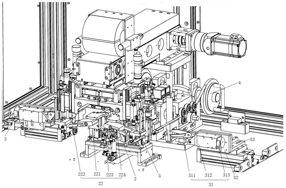
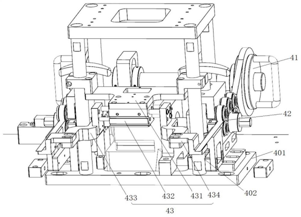
[0061] As shown in the figure, a busbar glue wrapping device integrating glue feeding and wrapping includes: a tape conveying device 4 and an automatic glue wrapping device 5. The tape conveying device 4 and the automatic glue wrapping device 5 are both located in On the workbench, the lower part of one end of the automatic glue wrapping device 5 is connected to the workbench through a group of uprights 402, and the automatic glue wrapping device 5 is arranged above the tape conveying device 4;

[0062] The adhesive tape conveying device 4 includes an adhesive tape placing rack 41, an adhesive tape conveying mechanism 42 and a conveying auxiliary mechanism 43. The adhesive tape placing rack 41 is arranged on a workbench, and a side of the adhesive tape placing rack 41 is installed on the workbench. Bottom plate 401, the tape conveying mechanism 42 is arranged on the mounting bottom plate 401, and a group of uprights 402 is arranged on the side of the mounting bottom plate 401 w...

Embodiment 2

[0076] The structure of the tape conveying device 4 and the automatic gluing device 5 described in this embodiment is the same as that in the first embodiment.

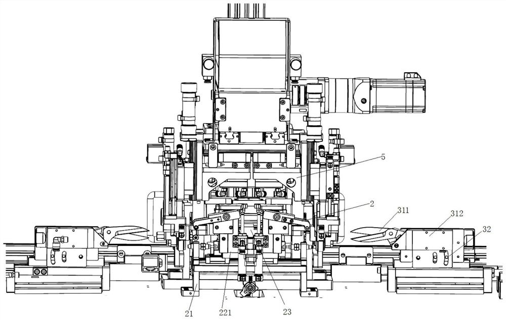
[0077] like figure 1 , 2 Shown is a busbar glue wrapping device integrating glue feeding and wrapping, further comprising: a tape smoothing device 2 and a tape cutting device 3, the tape smoothing device 2 is arranged in front of the tape conveying device 4 , and is located below the automatic glue wrapping device 5 , and the tape cutting device 3 is arranged on both sides of the tape smoothing device 2 .

[0078] like Figure 13-15 The tape smoothing device 2 shown includes a mounting seat 21, a set of smoothing devices 22 and a smoothing drive mechanism 23, wherein the smoothing device 22 includes a smoothing mounting seat 221, a smoothing mechanism 222 and a smoothing pressing mechanism 223, a set of guide rails 24 are arranged on the mounting seat 21, the smoothing mounting seat 221 is connected to the guide ra...

Embodiment 3

[0083] The tape leveling device 2, tape cutting device 3, tape conveying device 4 and automatic glue wrapping device 5 described in this embodiment are the same as the tape leveling device 2 and tape cutting device 3 in Embodiments 1 and 2. , The tape conveying device 4 and the automatic gluing device 5 have the same structure.

[0084] like Figures 19 to 23 Also shown is a busbar feeding and clamping device 1, the busbar feeding and clamping device 1 includes a product placement rack 12, a lift drive mechanism 13, a rotary clamping device 14 and an adsorption mechanism 15, the workbench 11 is provided with a set of guide rails 111, and a moving mechanism 16 is arranged below the product placement rack 12, the moving mechanism 16 is movably connected with the guide rails 111, and the elevating driving mechanism 13 is installed on the moving mechanism 16, and its output The end is connected with the product placing rack 12 , the rotating clamping device 14 is arranged on the ...


PUM


Abstract

The invention discloses a busbar adhesive tape winding device integrating adhesive tape conveying and adhesive tape winding, which comprises an adhesive tape conveying device and an automatic adhesive tape winding device, the adhesive tape conveying device and the automatic adhesive tape winding device are both arranged on a working table, the lower part of one end of the automatic adhesive tape winding device is connected with the working table through a group of upright posts, and the upright posts are arranged on the working table. And the automatic adhesive tape winding device is arranged above the adhesive tape conveying device. According to the busbar adhesive tape winding device integrating adhesive tape feeding and adhesive tape winding, adhesive tape feeding and adhesive tape winding are integrated through cooperation of the adhesive tape conveying device and the automatic adhesive tape winding device, automatic adhesive tape feeding is achieved, adhesive tape feeding and continuous adhesive tape supply are achieved, the adhesive tape feeding and winding efficiency is greatly improved, and the workload of workers is reduced; and the production requirements can be better met.

Description

technical field [0001] The invention belongs to the technical field of electrical processing, and particularly relates to a busbar glue wrapping device integrating glue collection, delivery and glue wrapping and a working method thereof. Background technique [0002] The busbar is also called the busbar, which refers to the connection copper or aluminum bar between the master switch in the electrical cabinet of the power supply system and the switch in each branch circuit. During the processing of the busbar, according to the requirements of its use, shielding sleeves need to be installed at both ends of the busbar. However, after the shielding sleeve is installed at the end of the busbar, the connection between the two cannot be completely sealed, which not only affects the stability of the connection. , it will also affect its shielding effect; and the busbar needs to be sprayed on its surface during processing, and some parts do not need to be sprayed, which is difficult ...

Claims


Application Information

Patent Timeline
Patent Type & Authority Applications(China)
IPC IPC(8): B65H23/34B65H35/00B65H35/07B65H16/02B65H20/16B65H81/06B65H19/28
CPCB65H23/34B65H35/008B65H35/06B65H16/02B65H20/16B65H81/06B65H19/283B65H2701/1722
Inventor 胡司晨杨建锋
Owner 苏州科伦特电气有限公司
Why Eureka
Try Eureka