Emergency unlocking device for locking mechanism of sliding plug door of urban rail vehicle

An emergency unlocking and purpose technology, which is applied in the field of emergency unlocking devices for passively locking urban rail doors, can solve the problems of unfavorable later maintenance, large space occupation, and lack of versatility

Pending Publication Date: 2021-01-01
CHANGCHUN UNIV OF TECH
View PDF12 Cites 4 Cited by
  • Summary
  • Abstract
  • Description
  • Claims
  • Application Information

AI Technical Summary

Problems solved by technology

[0003] The present invention is an emergency unlocking device that uses a combination of parts with high transmission efficiency and realizes the unlocking of a passive locking door mechanism by rotating a screw rod, and aims to solve the problems of low reliability, large space occupation, and inconvenient use of current emergency unlocking devices. It has defects such as versatility and relatively complex structure, which is not conducive to later maintenance; the technical solution of the present invention: it is characterized in that the emergency unlocking device is placed at the end of the screw, and the device is directly rotated by a kinematic pair connected with the screw The screw rod converts the original

Method used


Image

  • Emergency unlocking device for locking mechanism of sliding plug door of urban rail vehicle
  • Emergency unlocking device for locking mechanism of sliding plug door of urban rail vehicle
  • Emergency unlocking device for locking mechanism of sliding plug door of urban rail vehicle

Examples


Embodiment Construction

[0013] The present invention is described in further detail below in conjunction with accompanying drawing embodiment;

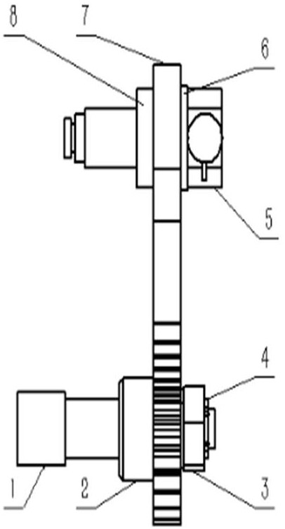
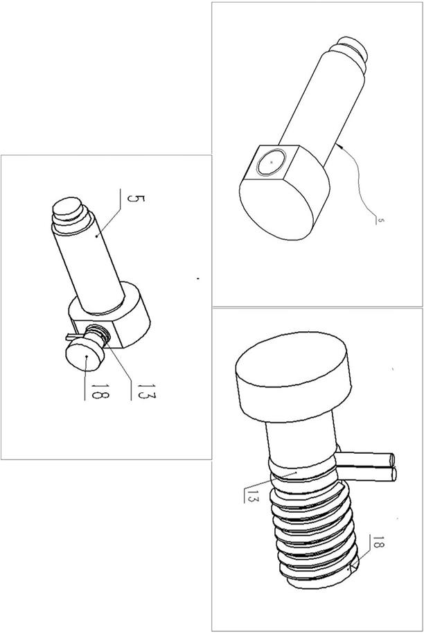
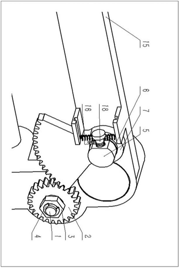
[0014] In the figure (1) is the screw, (2) is the screw gear, (3) is the lock nut, (4) is the retaining ring for the shaft, (5) is the rotating shaft, (6) is the sliding bearing, (7) It is a sector gear, (8) is a thrust sliding bearing, (9) is a fixed head, (10) is a plug connecting rod, (11) is a connecting frame, (12) is a short horizontal column, (13) is a wire rope, ( 14) is the internal operation to unlock the lock cylinder, (15) is the fixing frame, (16) is the spring, (17) is the wire rope fixing block, (18) is the reset component;

[0015] Such as figure 1 As shown, its structure is that the sector gear (7) is linked with the rotating shaft (5) through the sliding bearing (6) and the thrust sliding bearing (8), and the screw gear (2) is connected with the screw shaft (1) to rotate synchronously. The unlocking device The assembly location and main s...


PUM


Abstract

The invention relates to an emergency unlocking device for a locking mechanism of a sliding plug door of an urban rail vehicle. The emergency unlocking device for the locking mechanism of the slidingplug door of the urban rail vehicle is characterized in that the unlocking device is located at the end part of a screw rod and drives the screw rod through the rotation of a kinematic pair connectedwith the screw rod, so that the unlocking process of the mechanism is converted into the rotation process of the screw rod; and when the screw rod rotates by a certain angle, the mechanism is changedinto an unlocking state from a locking state, so that the unlocking action of the passive locking door mechanism is realized; and the kinematic pair is a sector gear and a screw rod gear, the lockingmechanism is unlocked through rotation after meshing, and therefore the unlocking purpose of the passive locking door mechanism is realized. The emergency unlocking device for the locking mechanism ofthe sliding plug door of the urban rail vehicle has the advantages of being simple in structure, small in occupied space and high in reliability and universality; and the structure can meet the dooropening requirement of emergency unlocking of an urban rail vehicle door system, and can be used for a sliding plug door driven by a motor-screw rod so as to realize unlocking operation in an emergency state to open the vehicle door.

Description

technical field [0001] What the present invention designs is a kind of emergency unlocking device suitable for the passive locking urban rail car door of screw transmission, because the passive locking door mechanism has the function of automatically locking the door mechanism when it is closed in place, so in an emergency , it is necessary to properly operate the emergency unlocking device to release the mechanical locking of the door mechanism, which belongs to the technical field of mechanical design. Background technique [0002] Due to the rapid development of the rail vehicle industry, the demand side has increasingly strict and demanding requirements for the purchased products. Since the emergency unlocking device is a very important part of the door mechanism, the reliability and safety of the operation process The requirements are higher; at the same time, with the rapid development of rail train door mechanisms, inner hidden doors, outer swing doors, and outer hang...

Claims


Application Information

Patent Timeline
IPC IPC(8): E05B85/00E05B83/36E05B77/02
CPCE05B85/00E05B83/363E05B77/02
Inventor 关英俊张铭起杨会生崔恒宫文彪曲慧东黄炜褀江昱含刘多
Owner CHANGCHUN UNIV OF TECH
Why Eureka
Try Eureka