Connecting structure and connecting method for parts at thin plate of atomizing and cooling dust remover

A connection structure and dust collector technology, applied in the direction of thin plate connection, connecting components, threaded fasteners, etc., can solve the problems of mechanical properties and sealing, the displacement of the center position of nuts and holes, and large-area deformation of plates. Achieve the effect of smooth and beautiful overall structure, reduce the workload of assembly and reduce the workload of welding

Active Publication Date: 2021-01-01
HUANGSHAN TIANZHIDU ENVIRONMENTAL SCI & TECH DEV CO LTD
View PDF6 Cites 4 Cited by
  • Summary
  • Abstract
  • Description
  • Claims
  • Application Information

AI Technical Summary

Problems solved by technology

[0002] At present, the combination of spray cooling and dust removal is used for the treatment of diesel engine exhaust, which requires a large number of welding nuts to fix small parts. Because the overall plate is relatively thin, a large area of ​​serious deformation is caused during the welding process; The shift of the center position will bring great difficulties to the subsequent assembly and also bring inconvenience to the later maintenance.
[0003] In addition, during the use of the dust collector, due to the pressure requirement, it is necessary to ensure the absolute sealing of the joints of the components. If ordinary screws and nuts are used to install the components on the thinner plate of the current dust collector, it will cause problems in mechanical properties and sealing. waiting to be solved

Method used


Image

  • Connecting structure and connecting method for parts at thin plate of atomizing and cooling dust remover
  • Connecting structure and connecting method for parts at thin plate of atomizing and cooling dust remover
  • Connecting structure and connecting method for parts at thin plate of atomizing and cooling dust remover

Examples


Embodiment Construction

[0041] The following will clearly and completely describe the technical solutions in the embodiments of the present invention with reference to the accompanying drawings in the embodiments of the present invention. Obviously, the described embodiments are only some, not all, embodiments of the present invention.

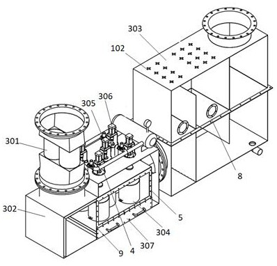
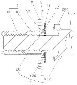
[0042] refer to Figure 1-7 , a connection structure of components at the thin plate of a spray cooling dust collector, including a blind rivet nut 1 and a blind rivet screw 2, the spray cooling dust collector specifically refers to a three-way catalytic converter 301, a pulse regeneration carbon black particle collection box 302 and The cooling horizontal spray box 303 is an integrated shell structure, the pulse regeneration carbon black particle collection box 302 is equipped with a DPF particle trap tank 304, and the top outlet of the DPF particle trap tank 304 is equipped with The lifting valve 305 and the blowback valve 306, the bottom outlet of the DPF particle...


PUM


Abstract

The invention discloses a connecting structure for parts at a thin plate of an atomizing and cooling dust remover. A rivet nut and a rivet screw are included, and the parts at the thin plate comprisea valve mounting flange, an inspection door plate, a sprayer mounting seat and an observation glass window mounting flange. The parts at the thin plate and the thin plate at the joint are provided with matched regular hexagonal through holes and matched regular circular through holes. The rivet nut comprises an internal thread section, a bent part and a flat flange. The rivet screw comprises an external thread section, a smooth cylindrical section and a screw cap, and the smooth cylindrical section is in cup joint with a boss ring and a sealing ring. A hexagonal groove and a sealing rubber layer are arranged on the top end surface of the sprayer mounting seat, a threaded groove is formed in the bottom of the hexagonal groove, and a hexagonal stainless steel sheet is arranged above the sprayer mounting seat. The invention further provides a corresponding connecting method. Installation of parts at all thin plates is simplified into the process that the two thin plates with the regular hexagonal through holes and the regular circular through holes are installed and fastened through rivet nuts and rivet screws, the installation efficiency is improved, the installation structure is attractive, and the sealing performance is good.

Description

technical field [0001] The invention relates to the technical field of installation of dust collector accessories, in particular to a connection structure and a connection method of components at the thin plate of a spray cooling dust collector. Background technique [0002] At present, the combination of spray cooling and dust removal is used for the treatment of diesel engine exhaust, which requires a large number of welding nuts to fix small parts. Because the overall plate is relatively thin, a large area of ​​serious deformation is caused during the welding process; The shift of the center position of the machine will bring great difficulties to the subsequent assembly and also bring inconvenience to the later maintenance. [0003] In addition, during the use of the dust collector, due to the pressure requirement, it is necessary to ensure the absolute sealing of the joints of the components. If ordinary screws and nuts are used to install the components on the thinner ...

Claims


Application Information

Patent Timeline
Patent Type & Authority Applications(China)
IPC IPC(8): F16B5/02F16B5/04F16B19/10F01N3/04F01N13/18
CPCF16B5/04F16B5/02F16B19/1072F01N3/04F01N13/1855
Inventor 王健江嗣中王辉占越洪鸣洪源继王鹏
Owner HUANGSHAN TIANZHIDU ENVIRONMENTAL SCI & TECH DEV CO LTD
Why Eureka
Try Eureka