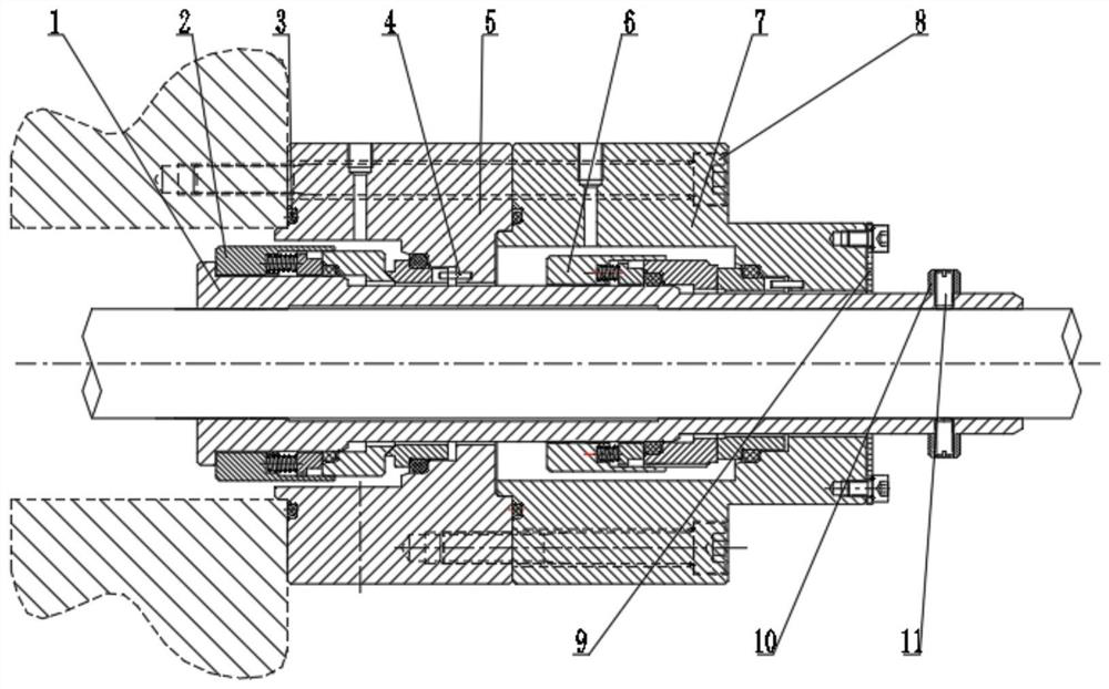
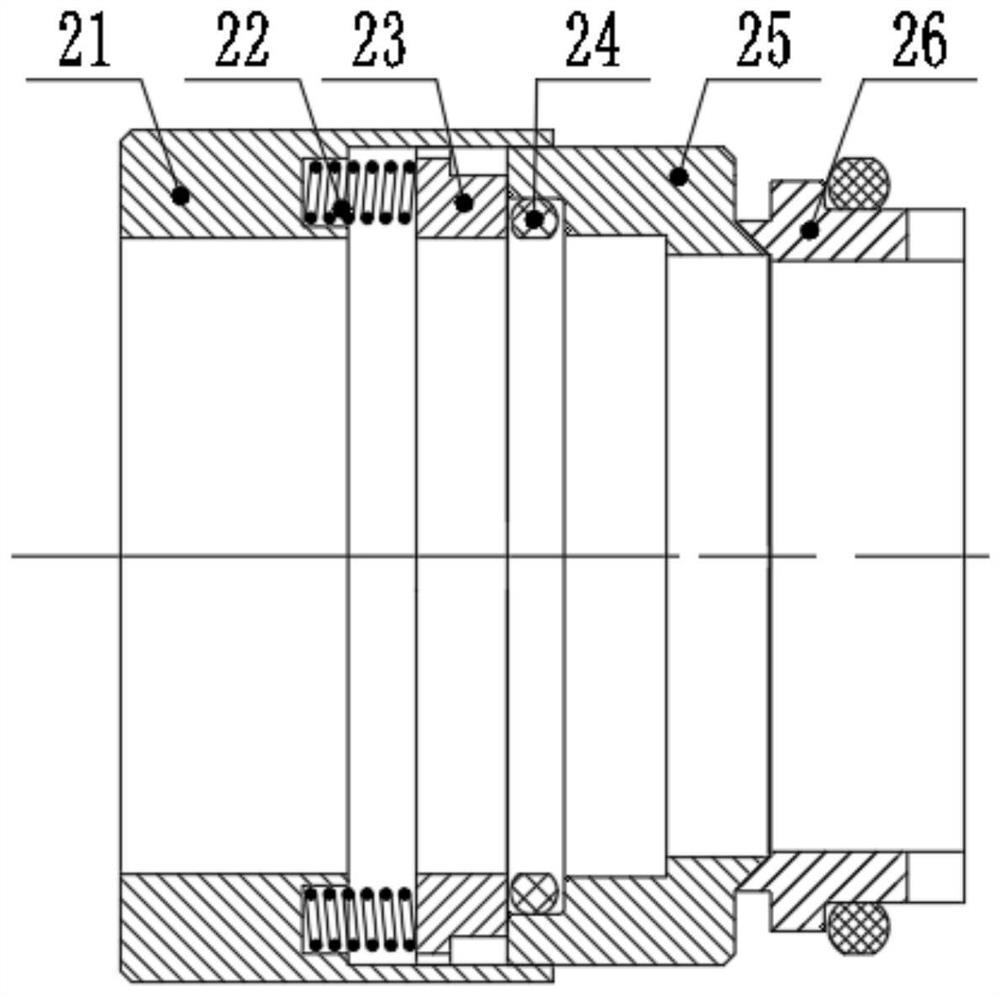
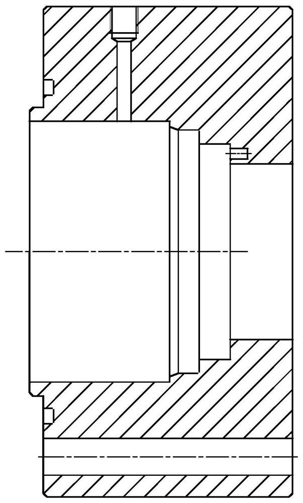
Two-stage conical surface-end surface series contact type mechanical sealing device for sewage pump
A technology of mechanical sealing device and sewage pump, which is applied in the direction of engine sealing, mechanical equipment, engine components, etc., can solve the problems that the sealing medium cannot be effectively prevented from leaking, and the sealing reliability is not satisfactory, so as to improve safety and stability , Reduce leakage, good heat dissipation effect
- Summary
- Abstract
- Description
- Claims
- Application Information
AI Technical Summary
Problems solved by technology
Method used
Image

Examples
Embodiment Construction
[0024] In order to make the object, technical solution and advantages of the present invention clearer, the present invention will be further described in detail below in conjunction with the accompanying drawings and embodiments. It should be understood that the specific embodiments described here are only used to explain the present invention, not to limit the present invention.
[0025] On the contrary, the invention covers any alternatives, modifications, equivalent methods and schemes within the spirit and scope of the invention as defined by the claims. Further, in order to make the public have a better understanding of the present invention, some specific details are described in detail in the detailed description of the present invention below. The present invention can be fully understood by those skilled in the art without the description of these detailed parts.
[0026] see Figure 1-5 , a two-stage cone-end series contact mechanical seal device for sewage pumps,...
PUM
 Abstract
Description
Claims
Application Information
PatSnap Eureka turns technology decisions into work you can execute. Powered by our Innovation Knowledge Graph, it runs expert workflows across engineering, life sciences, materials and intellectual property. Get your review-ready output in minutes.


