Transformer area fault positioning method and system based on marketing and distribution integration

A technology of fault location and station area, applied in the directions of fault location, fault detection by conductor type, transmission system, etc., can solve problems such as increasing fault location time, shorten fault location time, solve incomplete fault identification information, and increase operation and maintenance. The effect of workload

Pending Publication Date: 2021-01-01
NARI TECH CO LTD +1
View PDF0 Cites 4 Cited by
  • Summary
  • Abstract
  • Description
  • Claims
  • Application Information

AI Technical Summary

Problems solved by technology

[0005] The purpose of the present invention is to provide a fault location method based on multi-domain sensing information based on the integration of operation and distribution for fault location of the current low-voltage power distribution line, which relies on the participation of the main station personnel to increase the fault location time and delay the fault processing speed. system

Method used


Image

  • Transformer area fault positioning method and system based on marketing and distribution integration
  • Transformer area fault positioning method and system based on marketing and distribution integration
  • Transformer area fault positioning method and system based on marketing and distribution integration

Examples


Embodiment 1

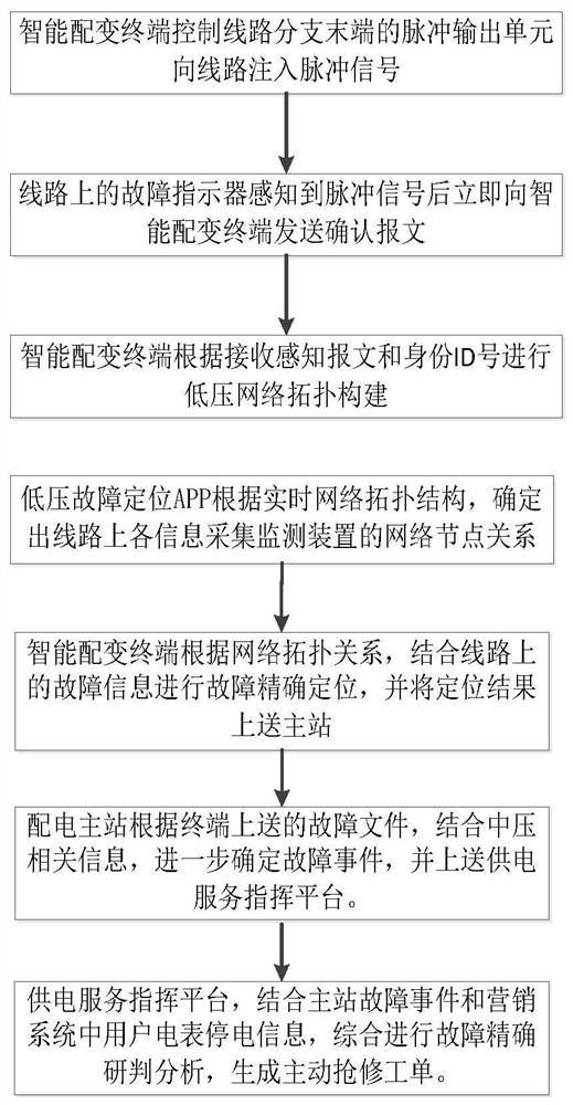
[0041] Embodiment 1. A method for locating faults in a station area based on the integration of operation and distribution includes the following steps:

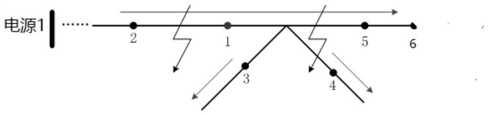
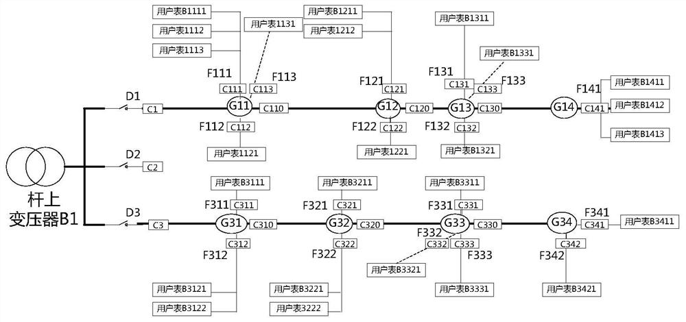
[0042] Inject the pulse signal from the end of the line branch, and receive the perception confirmation message and its identity sent by each fault indicator on the line in response to the pulse signal; according to the message and identity sent by each fault indicator on the line and the branch line The position of the exit circuit breaker determines the hierarchical relationship of the network topology; the network node relationship of each fault indicator and circuit breaker on the line is determined according to the network topology;

[0043] Based on the determined network node relationship, the fault is located according to the fault data sent by each fault indicator and circuit breaker when the fault occurs, and the fault location result of the station area is obtained.

[0044] The fault indicator described in this e...

Embodiment 2

[0046] Embodiment 2. On the basis of the embodiment, this embodiment optionally further includes the following step after identifying the network topology level: generating event alarms such as device change and topology update according to the identification result.

Embodiment 3

[0047] Embodiment 3. This embodiment provides a station area fault location method based on the integration of operation and distribution, including:

[0048] The pulse signal is injected from the end of the line branch, and the intelligent distribution transformer terminal receives the perception confirmation message and its identity sent by each fault indicator on the line in response to the pulse signal;

[0049] Determine the network topology hierarchy according to the message and identity sent by each fault indicator on the line and the position of the outlet circuit breaker on the branch line;

[0050] Determine the network node relationship of each fault indicator and circuit breaker on the line according to the network topology;

[0051] Based on the determined network node relationship, the fault is located according to the fault data sent by each fault indicator and circuit breaker when the fault occurs, and the fault location result of the station area is obtained. ...


PUM


Abstract

The invention discloses a transformer area fault positioning method and system based on marketing and distribution integration, and the method comprises the steps of injecting a pulse signal from thetail end of a line branch, and receiving a sensing confirmation message sent by each fault indicator on a line in response to the pulse signal and an identity label thereof; determining a network topology structure according to the message, the identity label and the position of an outlet circuit breaker on the branch line; and according to the network topology structure, determining a network node relationship between each fault indicator and the circuit breaker on the line and the fault data sent by each fault indicator and the circuit breaker when a fault occurs, and positioning the fault to obtain a transformer area fault positioning result. According to the invention, the marketing and distribution information sharing is realized, and the problems of incomplete fault identification information and difficult positioning of the low-voltage distribution area are effectively solved, thereby realizing the rapid fault positioning of the low-voltage distribution area, reducing fault hidden troubles, and improving the power supply reliability of users.

Description

technical field [0001] The invention relates to the field of electric power system and its automation, in particular to a fault location method and system in a station area based on the integration of operation and distribution. Background technique [0002] Medium and low voltage power distribution lines have the characteristics of large power supply area, many electrical equipment associations, and complex operating environment. Defects such as equipment renewal and maintenance, large amount of engineering, and slow response speed make the probability of distribution line failures on the rise, which has a very negative impact on the safe and stable operation of the power grid and the image of power supply companies in society. [0003] At present, there are mainly two methods for fault location of low-voltage distribution lines: (1) Distribution network fault section location method based on fault indicators, that is, fault indicators are installed along the distribution n...

Claims


Application Information

Patent Timeline
Patent Type & Authority Applications(China)
IPC IPC(8): G01R31/08G01R31/52H04L12/24
CPCG01R31/086G01R31/52H04L41/0677
Inventor 吴海胡国王小红黄峰谭阔鲍柏舟王辉戴申鉴
Owner NARI TECH CO LTD
Why Eureka
Try Eureka