Device for introducing implants

A technology for implants, internal implants, applied in the field of devices for introducing implants, which can solve problems such as blocking blood flow, compressing implant size limitations, damaging the walls of blood vessels, etc.

Pending Publication Date: 2021-01-01
PHENOX
View PDF2 Cites 0 Cited by
  • Summary
  • Abstract
  • Description
  • Claims
  • Application Information

AI Technical Summary

Problems solved by technology

Both this proximal portion and the aforementioned connecting elements may have deleterious effects after the implant has been placed, for example, by protruding into the lumen of the blood vessel and blocking blood flow, damaging the wall of the blood vessel, or causing other problems
[0005] Furthermore, in the case of conventionally inserted implants

Method used


Image

  • Device for introducing implants
  • Device for introducing implants
  • Device for introducing implants

Examples


Embodiment Construction

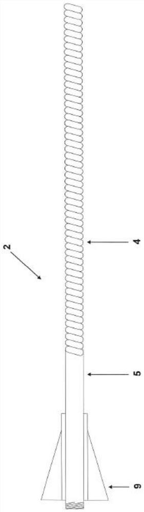
[0054] exist figure 1 In , the shaft 2 , as part of the device proposed by the present invention, is shown in side view, wherein in the selected representative illustration left means proximal and right means distal. On the shaft 2 there is a proximal region 5 of considerable stiffness and a flexible coil 4 forming the distal region of the shaft 2, the proximal end of which is formed as a connecting element 9 in the form of a wire luer lock connector.

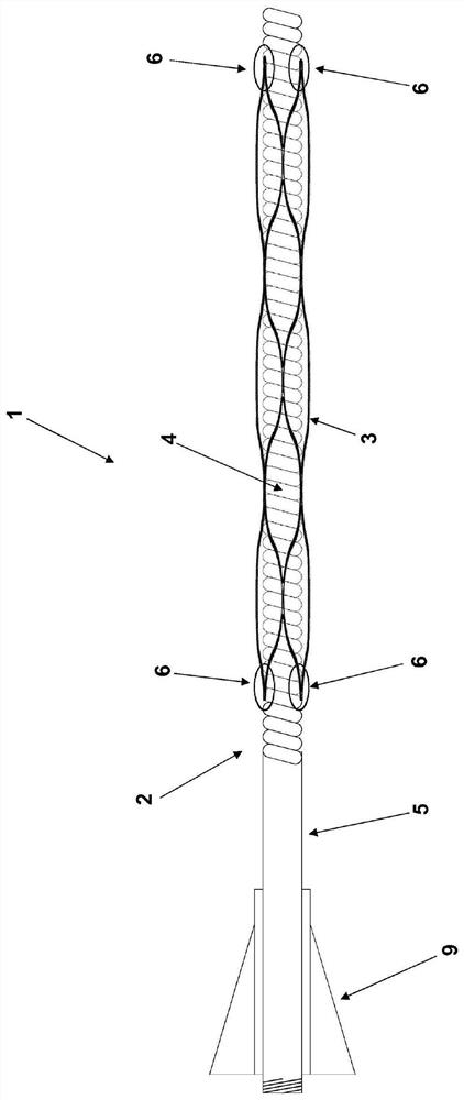
[0055] figure 2 A device 1 according to a first embodiment is shown. In this case, the shaft 2 carries an implant 3 consisting of a laser-cut stent. The implant 3 is connected to the coil 4 of the shaft 2 by means of several connection points 6 . The connection points 6 are of adhesive design and can be detached by applying a solvent. Since the gaps between the windings of the coil 4 are sufficiently permeable, solvent can be brought to the connection point 6 through the inside of the shaft 2 .

[0056] Once the connectio...


PUM


Abstract

The invention relates to a device (1) for introducing endovascular implants (3), which have an at least partly cylindrical design, into blood vessels, wherein the implant (3) is provided in an expanded state, in which the implant is placed in the blood vessel, and in a compressed state, in which the implant can be introduced into the blood vessel, and the device (1) has an elongated shaft (2), theexterior of which is releasably secured to the implant (3) in the compressed state and through which the implant (3) runs. The implant (3) has at least one respective connection point (6) to the shaft (2) proximally and distally, said connection point being thermally, chemically, or electrolytically releasable; or at least one thread (12) extends in the longitudinal direction over the implant (3)at least over a majority of the length of the implant (3) such that the implant (3) is secured to the shaft (2) in the compressed state, and the thread (12) has at least one respective connection point (10, 11) to the shaft (2) proximally and distally, at least one connection point (11) of the connection points being thermally, chemically, or electrolytically releasable.

Description

technical field [0001] The invention relates to a device for introducing an intravascular implant of at least partially cylindrical design into a blood vessel, wherein the implant is provided in an expanded state and a compressed state, in which the implant is placed In a blood vessel, in a compressed state, an implant can be introduced into the blood vessel, wherein the device has an elongated shaft, the implant is secured in the compressed state on the outside of the elongated shaft, so that the implant is detachable, And the shaft extends through the implant. Background technique [0002] The placement of endovascular implants into blood vessels such as arteries, veins, aneurysms or other vascular malformations is well known in the art. In this regard, for example, stents are implanted in blood vessels to keep them open permanently. Other examples of such devices include occlusive coils that are inserted into the aneurysm to fill the aneurysm and induce thrombus formati...

Claims


Application Information

Patent Timeline
IPC IPC(8): A61F2/95
CPCA61F2/95A61F2002/9505A61F2250/0071A61F2002/9511
Inventor H·亨克斯R·汉内斯H·蒙斯塔特
Owner PHENOX
Why Eureka
Try Eureka