
Mixing device for glue production

A mixing device and glue technology, used in mixers, transportation and packaging, shaking/oscillating/vibrating mixers, etc., can solve the problems of single mixing method and poor mixing effect, and improve safety and facilitate manual operation. Open, practical effect

Inactive Publication Date: 2021-01-05
路婷婷
View PDF0 Cites 1 Cited by
  • Summary
  • Abstract
  • Description
  • Claims
  • Application Information

AI Technical Summary

Problems solved by technology

[0003] In the existing technology, the mixing method used by the mixing device for glue production is relatively simple. Most of them use the motor to drive the stirring shaft to drive the stirring blade to stir the materials, and the materials at the same position are stirred, resulting in poor mixing effect.

Method used


Image

  • Mixing device for glue production
  • Mixing device for glue production
  • Mixing device for glue production

Examples


Embodiment 1

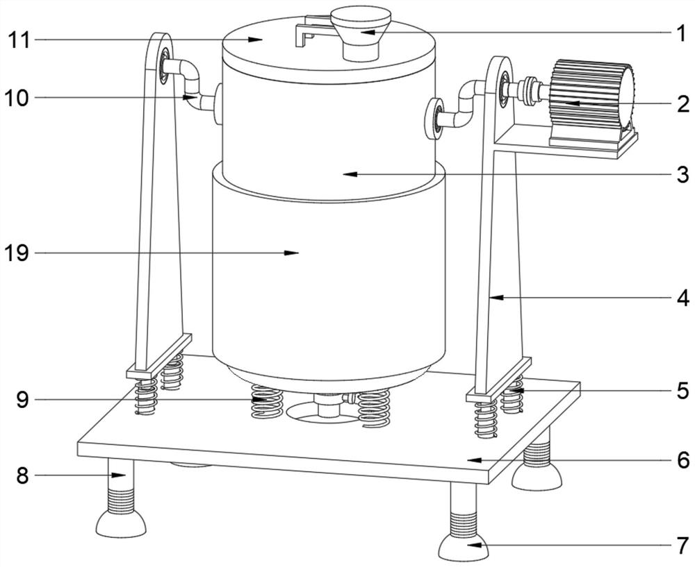
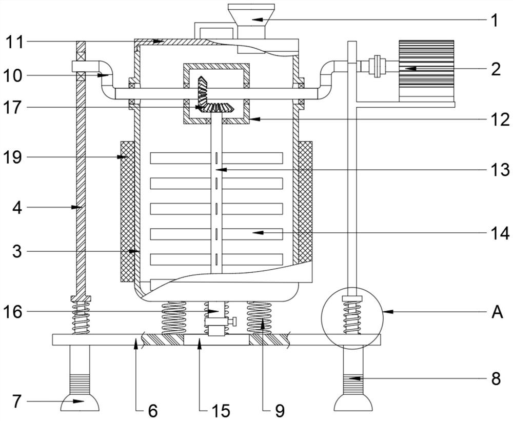
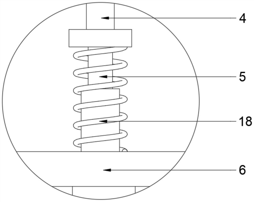
[0025] see Figure 1~3 , in an embodiment of the present invention, a mixing device for glue production, comprising a mixing frame and a mixing tank 3 and a mixing device installed on the mixing frame, the mixing frame includes a support frame 4 and The frame bottom plate 6, the number of the support frame 4 is two groups and is installed on the frame bottom plate 6 by a shaking device, the mixing bucket 3 is installed on the support frame 4 by a mixing device and a heating device 19 is arranged on its periphery , the top of the mixing tank 3 is also communicated with a feed hopper 1, through which materials are added to the inside of the mixing tank 3; the mixing device includes a drive crankshaft 10, a conversion shell 12 and a stirring shaft 13. The mixing tank 3 is connected in rotation with the transmission crankshaft 10, and the two ends of the transmission crankshaft 10 are mounted on two sets of support frames 4 through bearings, and one end of the transmission cranksh...

Embodiment 2

[0032] see figure 1 , 2 , 4. In the embodiment of the present invention, a mixing device for glue production, in order to prevent the mixing tank 3 from deflecting during work and affecting the work of the mixing device, on the basis of Example 1, the mixing tank 3. The bottom is also provided with limit springs 9. The number of the limit springs 9 is three groups and is evenly distributed in the periphery of the discharge port 15 in a ring shape. The three sets of limit springs 9 are fixed at one end away from the mixing barrel 3 On the frame bottom plate 6; when the drive motor 2 drives the mixing tank 3 to move up and down through the transmission crankshaft 10, the limit spring 9 expands and contracts with the mixing tank 3 up and down, and simultaneously limits the outward deflection of the mixing tank 3, The collision between the mixing blade 14 and the inner wall of the mixing tank 3 is avoided to improve safety.

[0033] The working principle of the present invention...


PUM


Abstract

The invention discloses a mixing device for glue production, which comprises a mixing rack, and a mixing barrel and a mixing device which are arranged on the mixing rack, the mixing rack comprises a support frame and a rack bottom plate, the mixing device comprises a transmission crankshaft, a conversion shell and a stirring rotating shaft, the mixing barrel is rotationally mounted on the supporting frame through the transmission crankshaft, the transmission crankshaft and the driving motor are arranged in a linkage manner, the stirring rotating shaft and the transmission crankshaft are arranged in a linkage manner through a conversion shell and a bevel gear set, and multiple sets of stirring blades are fixedly mounted at the lower end of the stirring rotating shaft. The mixing barrel, thestirring rotating shaft and the stirring blades are matched with the transmission crankshaft, the bevel gear set and the driving motor to drive the mixing barrel to move up and down, so that materials in the mixing barrel shake, and the shaking device is matched, so that the mixing barrel and the mixing device integrally form inertia shaking, material mixing is promoted, and meanwhile, the stirring rotating shaft is driven to rotate; the materials are stirred by the stirring blades, therefore, material mixing is promoted, and the reaction process is accelerated.

Description

technical field [0001] The invention relates to the technical field of glue production, in particular to a mixing device for glue production. Background technique [0002] Glue is a substance that can bond two objects. It usually appears as a water solution and is processed from a variety of raw materials. During the production and processing of glue, a mixing device with a stirring function is often used. [0003] In the existing technology, the mixing method used by the mixing device for glue production is relatively simple. Most of them use the motor to drive the stirring shaft to drive the stirring blade to stir the materials, and the materials at the same position are stirred, resulting in poor mixing effect. . Therefore, we provide a mixing device for glue production. Contents of the invention [0004] The purpose of the present invention is to provide a mixing device for glue production to solve the problems raised in the above-mentioned background technology. ...

Claims


Application Information

Patent Timeline
Patent Type & Authority Applications(China)
IPC IPC(8): B01F11/00B01F15/00B01F15/02
CPCB01F31/56B01F35/31B01F35/3204B01F35/42B01F35/45B01F35/71731B01F2101/36
Inventor 路婷婷
Owner 路婷婷
Learn More