Automatic argon arc welding device

An argon arc welding and automatic technology, applied in welding equipment, welding accessories, arc welding equipment, etc., can solve problems such as difficult to achieve continuous welding and errors in manual operation, so as to improve welding quality, high welding precision and improve work efficiency. efficiency effect

Inactive Publication Date: 2021-01-05
曾宝香
View PDF7 Cites 5 Cited by
  • Summary
  • Abstract
  • Description
  • Claims
  • Application Information

AI Technical Summary

Problems solved by technology

[0004] 1. During welding, the hand-held welding torch needs to be swayed at a constant speed from left to right along the weld seam, so that the weld seam is uniform and firm. At this time, manual precise operation is required, which is obviously difficult to achieve, and there will be errors in manual operation;
[0005] 2. Continuous welding is required during welding, so that the effect or quality of welding can be guaranteed. However, manual hand-held welding torches will be affected by the welding light and it is obviously difficult to achieve continuous welding.

Method used


Image

  • Automatic argon arc welding device
  • Automatic argon arc welding device
  • Automatic argon arc welding device

Examples


Embodiment Construction

[0037] The following will clearly and completely describe the technical solutions in the embodiments of the present invention with reference to the accompanying drawings in the embodiments of the present invention. Obviously, the described embodiments are only some, not all, embodiments of the present invention.

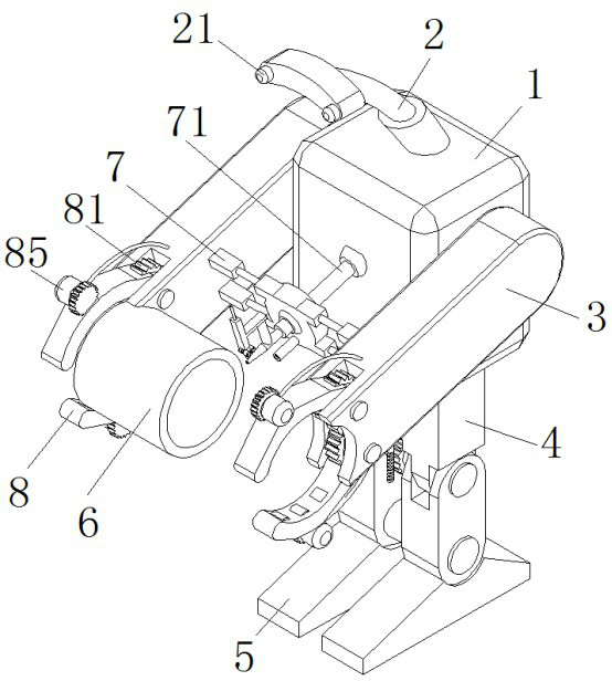
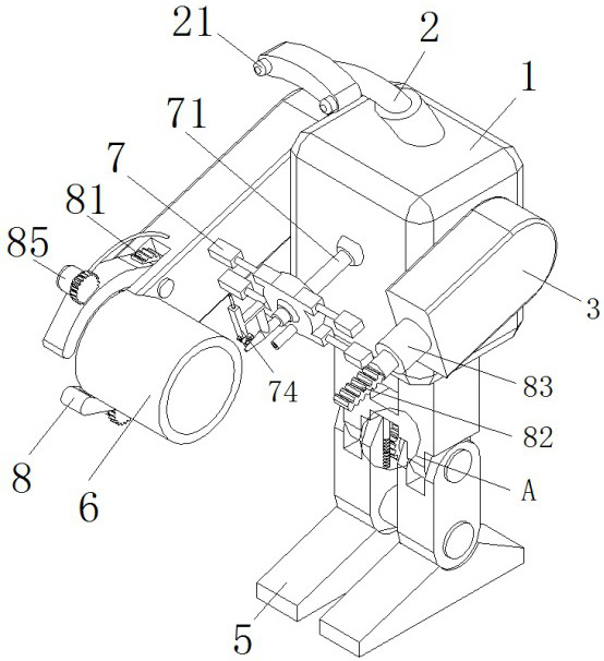
[0038] refer to Figure 1-5 , an automatic argon arc welding device, including a robot, the robot is composed of a body 1, a mechanical head, a mechanical arm 3, a mechanical leg 4 and a mechanical foot 5, the inner surface of the mechanical leg 4 is fixedly installed with a squatting mechanism, and the squatting mechanism controls The bending degree between the mechanical leg 4 and the mechanical foot 5;

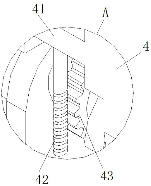
[0039] Further, the squatting mechanism includes a servo motor 41, which is fixedly installed on the inner surface of the mechanical leg 4, and the output shaft of the servo motor 41 is fixedly installed with a worm 42 through a coupling.

[0040] Further, the me...


PUM


Abstract

The invention belongs to the technical field of argon arc welding device, and particularly relates to an automatic argon arc welding device. The automatic argon arc welding device comprises a robot, wherein the robot is composed of a robot body, a mechanical head, mechanical arms, mechanical legs and mechanical feet, wherein a squatting and bending mechanism is fixedly installed on the inner sidesurface of each mechanical leg, and the squatting and bending mechanisms control the bending degree between the mechanical legs and the mechanical feet. Manipulators are fixedly mounted at the bottomends of the mechanical arms, the manipulators are hinged to welded pieces and clamp the welded pieces, and the manipulators drive the welded pieces to rotate. A welding mechanism is fixedly installedright in front of the robot body, and the two sides of the welding mechanism are fixedly connected with the inner side surfaces of the mechanical arms through miniature hydraulic cylinders. Accordingto the automatic argon arc welding device, through the arrangement of the welding mechanism, the effect of conducting small-amplitude swing welding on the welding seam between the welded pieces is achieved, the welded pieces rotate during welding, in cooperation with the miniature hydraulic cylinders and a telescopic hydraulic cylinder which control a welding gun, the width of the welding seam iscontrolled by the miniature hydraulic cylinders, the welding thickness of the welding seam is controlled by the telescopic hydraulic cylinder, and then the effect of accurate, constant-speed and continuous welding is achieved.

Description

technical field [0001] The invention relates to the technical field of argon arc welding equipment, in particular to an automatic argon arc welding device. Background technique [0002] Argon arc welding technology is based on the principle of ordinary arc welding, using argon gas to protect the metal welding material, and through high current to make the welding material melt into a liquid state on the base material to be welded to form a molten pool, so that the welded metal and the welding material It is a welding technology that achieves metallurgical combination of materials. Since argon gas is continuously supplied during high-temperature fusion welding, the welding materials cannot be in contact with oxygen in the air, thereby preventing the oxidation of the welding materials. Therefore, stainless steel and iron metals can be welded. . [0003] When the existing argon arc welding equipment is used, most of them are hand-held welding torches, and the workpiece is rota...

Claims


Application Information

Patent Timeline
Patent Type & Authority Applications(China)
IPC IPC(8): B23K9/16B23K9/28B23K9/32
CPCB23K9/16B23K9/28B23K9/32
Inventor 马江南
Owner 曾宝香
Why Eureka
Try Eureka