
Automatic finned tube welding device convenient to fix

An automatic welding and finned tube technology, which is applied in the field of finned tube welding, can solve the problems of strip fin welding and fixing welding devices, time-consuming and labor-intensive problems, and achieve the effects of convenient operation, reduced labor, and convenient welding and fixing

Active Publication Date: 2021-01-05
江苏鼎翔节能科技有限公司
View PDF7 Cites 4 Cited by
  • Summary
  • Abstract
  • Description
  • Claims
  • Application Information

AI Technical Summary

Problems solved by technology

[0002] Finned tube is a kind of heat exchange element, in order to improve the heat exchange efficiency, usually fins are added on the surface of the heat exchange tube to increase the outer surface area of ​​the heat exchange tube, so as to achieve the purpose of improving the heat exchange efficiency, the finned tube In the process of processing, it is necessary to use welding devices to weld the fins on the heat exchange tubes. Nowadays, most of the welding devices are to weld the fins on the finned tubes, and there is no special welding and fixing of the strip fins. The welding device on the outer wall of the finned tube needs to be loaded individually during the welding process, which is time-consuming and laborious

Method used


Image

  • Automatic finned tube welding device convenient to fix
  • Automatic finned tube welding device convenient to fix
  • Automatic finned tube welding device convenient to fix

Examples


Embodiment Construction

[0027]The following will clearly and completely describe the technical solutions in the embodiments of the present invention with reference to the accompanying drawings in the embodiments of the present invention. Obviously, the described embodiments are only some, not all, embodiments of the present invention. Based on the embodiments of the present invention, all other embodiments obtained by persons of ordinary skill in the art without making creative efforts belong to the protection scope of the present invention.

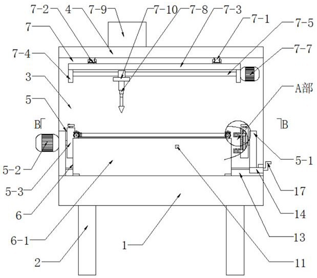
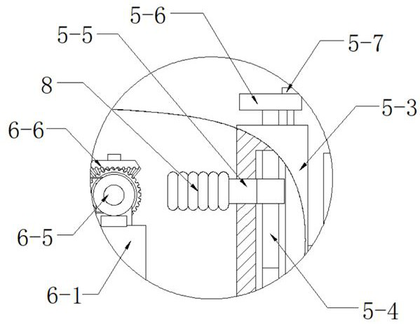
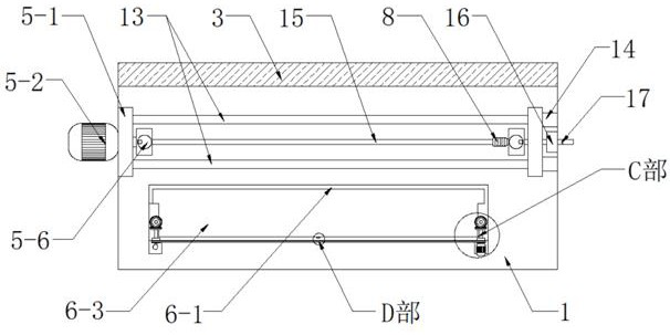
[0028] Such as Figure 1-Figure 7 As shown, the present embodiment adopts the following technical scheme: it comprises a workbench 1, a support foot 2, a support plate 3 and a top plate 4, the four corners of the lower surface of the workbench 1 are welded and fixed with the support feet 2, and The rear side is welded and fixed with a support plate 3, and the upper side of the front side wall of the support plate 3 is welded and fixed with a top plate 4, which ...


PUM


Abstract

The invention discloses an automatic finned tube welding device convenient to fix, and relates to the technical field of finned tube welding. Supporting legs are fixed to the four corners of the lowersurface of a workbench, a supporting plate is fixed to the rear side of the upper surface of the workbench, and a top plate is fixed to the upper side of the front side wall of the supporting plate and suspended above the workbench. The device further comprises a fixing mechanism, a feeding mechanism and a welding mechanism, the fixing mechanism is arranged in the center of the upper surface of the workbench, fixing plates in the fixing mechanism are arranged on the left side and the right side of the upper surface of the workbench, the feeding mechanism is arranged on the front side of the upper surface of the workbench, a storage box in the feeding mechanism is arranged on the upper surface of the workbench, the welding mechanism is suspended above the feeding mechanism, and first sliding rails in the welding mechanism are fixed to the left side and the right side of the lower surface of the top plate correspondingly. In the welding process, automatic feeding can be achieved, manualsingle feeding is not needed, and therefore the labor amount of workers is reduced, the time-saving and labor-saving effects are achieved, and the automatic finned tube welding device has the advantages of being reasonable in arrangement, low in manufacturing cost and the like.

Description

technical field [0001] The invention relates to the technical field of fin tube welding, in particular to an automatic fin tube welding device which is convenient for fixing. Background technique [0002] Finned tube is a kind of heat exchange element, in order to improve the heat exchange efficiency, usually fins are added on the surface of the heat exchange tube to increase the outer surface area of ​​the heat exchange tube, so as to achieve the purpose of improving the heat exchange efficiency, the finned tube In the process of processing, it is necessary to use welding devices to weld the fins on the heat exchange tubes. Nowadays, most of the welding devices are to weld the fins on the finned tubes, and there is no special welding and fixing of the strip fins. The welding device on the outer wall of the finned tube needs to be loaded individually during the welding process, which is time-consuming and laborious. Contents of the invention [0003] The object of the pre...

Claims


Application Information

Patent Timeline
Patent Type & Authority Applications(China)
IPC IPC(8): B23K31/02B23K37/04B23K37/00
CPCB23K31/02B23K37/00B23K37/0426
Inventor 陆海军陆国祥周卫荣
Owner 江苏鼎翔节能科技有限公司
Learn More