Positioning device, positioning structure and construction method of steel bar fixture for steel cage roll welding machine

A technology of positioning device and steel cage, which is applied in auxiliary devices, welding equipment, manufacturing tools, etc., can solve the problems of time-consuming accuracy and low accuracy, and achieve the effects of high installation accuracy, simplified production process, and improved processing efficiency.

Active Publication Date: 2022-02-22
中国建筑土木建设有限公司
View PDF0 Cites 0 Cited by
  • Summary
  • Abstract
  • Description
  • Claims
  • Application Information

AI Technical Summary

Problems solved by technology

[0003] The purpose of the present invention is to provide a positioning device, a positioning structure and a construction method for a steel bar fixture of a steel cage roll welding machine, so as to solve the problem that the steel cage roll welding machine in the prior art needs to stop in place when processing steel cages with different diameters and different numbers of main bars To replace the fixture, the worker holds a ruler to adjust the distance between the fixtures. The process is time-consuming and the accuracy is not high.

Method used


Image

  • Positioning device, positioning structure and construction method of steel bar fixture for steel cage roll welding machine
  • Positioning device, positioning structure and construction method of steel bar fixture for steel cage roll welding machine
  • Positioning device, positioning structure and construction method of steel bar fixture for steel cage roll welding machine

Examples


Embodiment Construction

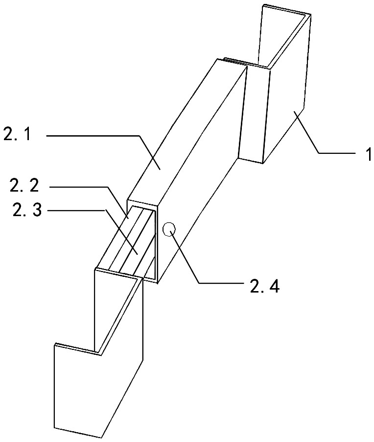
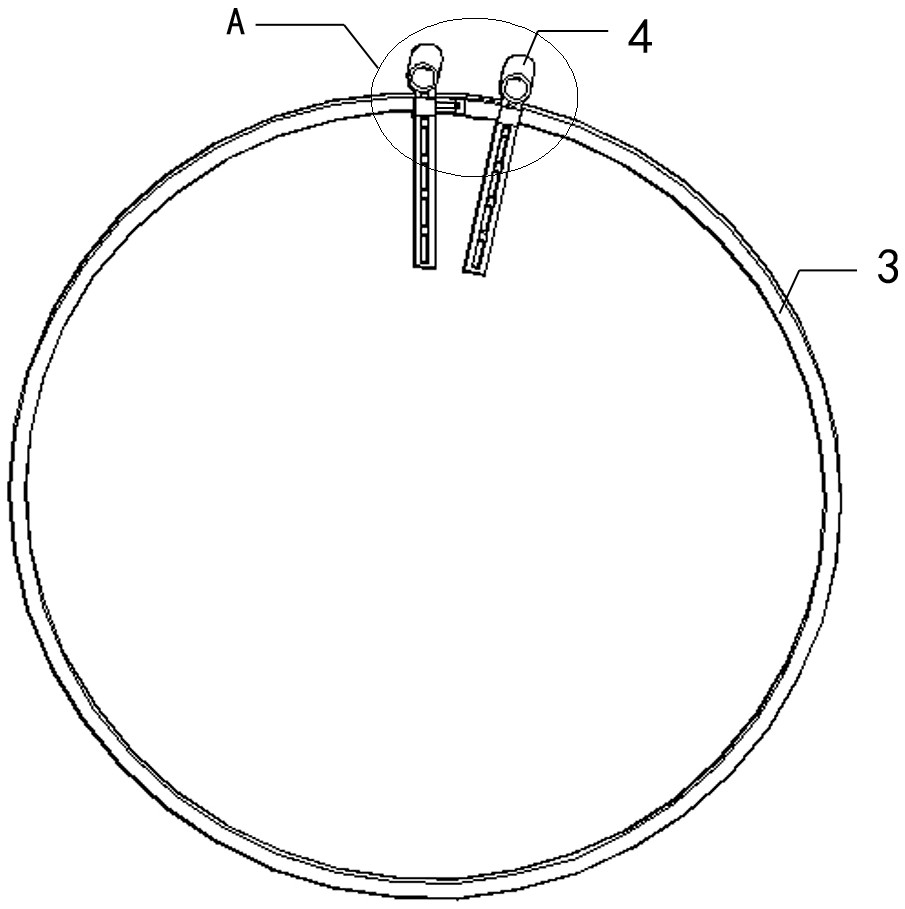
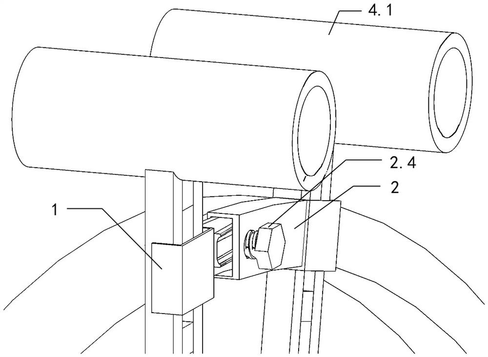
[0068] Examples see figure 1 As shown, the positioning device, positioning structure and construction method of the steel bar fixture of the steel cage roll welding machine of the present invention, the positioning device of the steel bar roll welding machine steel bar clamp is in the shape of an arc as a whole, including two U-shaped slots 1 arranged side by side And the chute 2 connected between the two U-shaped slots 1; wherein the U-shaped slot 1 is a channel steel; the chute 2 includes an outer sleeve 2.1 with a rectangular arc shape in cross section and an adaptive movable plug in The cross-section of the outer sleeve 2.1 is a rectangular arc-shaped inner block 2.2, the inner side of the inner block 2.2 is closely attached to the inner inner wall of the outer sleeve 2.1; the middle part of the outer side of the inner block 2.2 is arranged through the long axis A C-shaped block 2.3 is fixedly connected, and the opening of the C-shaped block 2.3 is set outward; the outer ...


PUM

PropertyMeasurementUnit
diameteraaaaaaaaaa
diameteraaaaaaaaaa
diameteraaaaaaaaaa

Abstract

The positioning device, positioning structure and construction method of the steel bar fixture of the steel cage roll welding machine relate to the field of pile foundation steel bar processing. The chute between the card slots. The chute includes an outer sleeve with a rectangular arc shape in cross section and an inner block with a rectangular arc shape in cross section that is adapted to be movably inserted into the outer sleeve. Adjacent; the middle part of the outer surface of the inner inserting block is fixedly connected with a C-shaped clamping block along the long axis. Go through the bolt holes and tighten on the C-shaped clamping block. The invention solves the problems in the prior art that when a steel cage roll welder processes steel cages with different diameters and different numbers of main bars, it needs to be stopped to replace the clamps in place, and workers hold a ruler to adjust the distance between the clamps. The process is time-consuming and has low precision.

Description

technical field [0001] The invention relates to the field of pile foundation steel cage processing, in particular to a positioning device, a positioning structure and a construction method for a steel bar clamp of a steel bar cage roll welding machine. Background technique [0002] When the steel cage roll welding machine is processing steel cages with different diameters and different numbers of main bars, it needs to stop and replace the fixtures in place. The workers hold a ruler to adjust the distance between the fixtures. The process is time-consuming and the accuracy is not high. Therefore, it is necessary to propose a method that can realize the rapid installation, disassembly and positioning adjustment of the main reinforcement of the steel cage without delaying the production schedule. Contents of the invention [0003] The purpose of the present invention is to provide a positioning device, a positioning structure and a construction method for a steel bar fixture...

Claims


Application Information

Patent Timeline
Patent Type & Authority Patents(China)
IPC IPC(8): B21F27/12B23K37/04B23K37/00B23K103/04
CPCB23K37/0443B23K37/00B21F27/12B23K2103/04
Inventor 吕柏行郭志光敖长江刘斌张凡
Owner 中国建筑土木建设有限公司
Why Eureka
Try Eureka