Automatic rubber head replacing mechanism of pad printing machine

A technology for automatic replacement and pad printing, applied in printing presses, rotary printing presses, printing and other directions, can solve the problems of occupying printing equipment space, low degree of automation, troublesome operation, etc., to reduce the failure rate, save plane space occupation, Precise effect of station adjustment

Active Publication Date: 2021-01-05
深圳市久和丝印器材有限公司
View PDF6 Cites 3 Cited by
  • Summary
  • Abstract
  • Description
  • Claims
  • Application Information

AI Technical Summary

Problems solved by technology

[0002] In the surface printing and decoration industry, pattern printing on a large number of soft material surfaces and uneven surfaces must use pad printing technology due to the surface shape, and printing of high-definition patterns and precise color registration patterns can only meet the requirements of pad printing technology. The surface pad printing process covers almost most of the industrial and civil products; with the continuous improvement of product quality requirements, more and more types of products need to be surface pad printed, but the current degree of automation of the equipment in the pad printing industry is very low, almost All are semi-automatic single-station production models, which are difficult to adapt to the current market demand for small batches and multiple varieties. The automation level of pad printing machines needs to be improved urgently.
[0003] The current pad printing machine adopts a single-station but rubber head processing method. For different printing patterns, printing equipment with different rubber heads is required. If you want to replace the printing rubber head, it is more common to replace it manually, and the method is relatively backward. , the operation is more troublesome, and now there are pad printers that can automatically replace the rubber head on the market, but the storage of the rubber head is flat, and it is necessary to control the printing end of the pad printer to match the position of the rubber head that needs to be replaced. This method not only needs to program more alignment programs, but also the planar rubber head storage library occupies a limited space of the printing equipment

Method used


Image

  • Automatic rubber head replacing mechanism of pad printing machine
  • Automatic rubber head replacing mechanism of pad printing machine
  • Automatic rubber head replacing mechanism of pad printing machine

Examples


Embodiment Construction

[0030] The present invention will be further described below in conjunction with the accompanying drawings and embodiments.

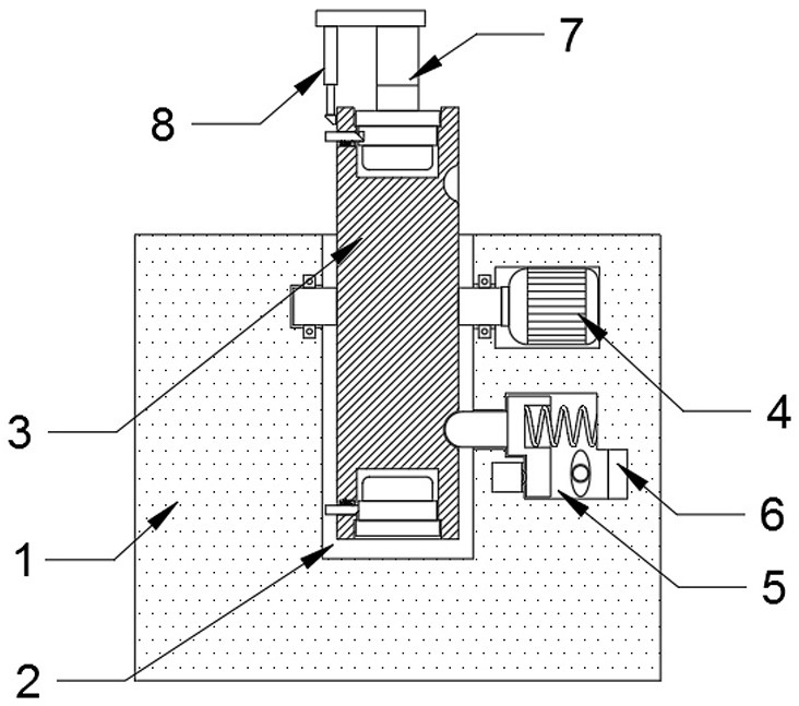
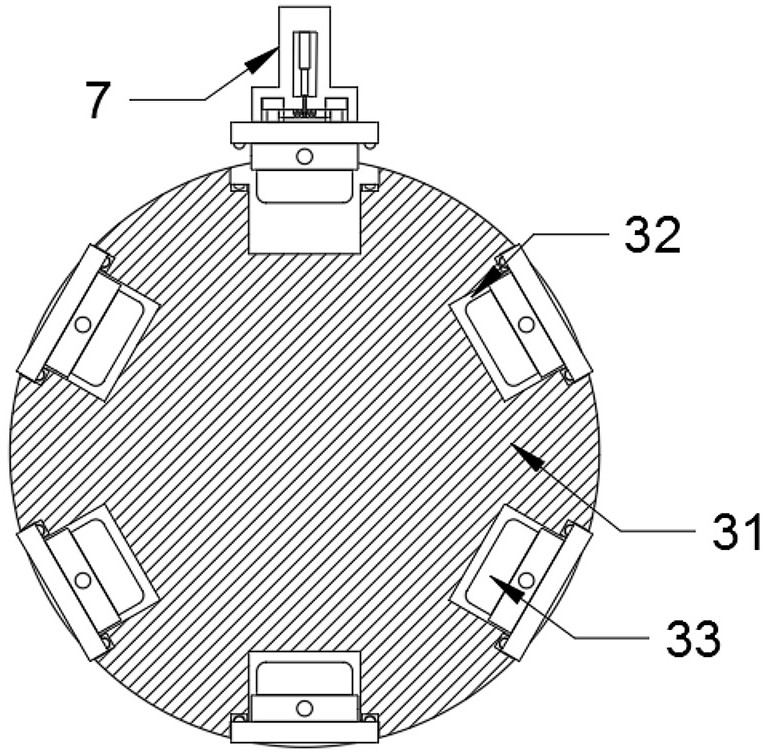
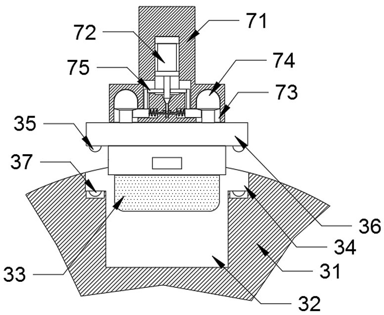
[0031] Please refer to figure 1 , figure 2 , image 3 , Figure 4 , Figure 5 , Figure 6 , Figure 7 and Figure 8 ,in, figure 1 A schematic diagram of the overall cross-sectional structure provided by the present invention; figure 2 Schematic diagram of the structure of the rubber head library assembly provided by the present invention; image 3 Schematic diagram of the cooperative structure of the printing head assembly and the rubber head library assembly provided by the present invention; Figure 4 Structural schematic diagram of the clamping mechanism and the fastening mechanism provided by the present invention; Figure 5 One of the structural schematic diagrams of the locking assembly provided by the present invention; Figure 6 The second schematic diagram of the structure of the locking assembly provided by the present invention; ...


PUM


Abstract

The invention provides an automatic rubber head replacing mechanism of a pad printing machine. The mechanism comprises a machining table, a mounting groove and a motor, the mounting groove is formed in the surface of the machining table, the motor is mounted in the machining table and located on the side edge of the mounting groove, a disc-shaped rotatable rubber head library assembly is mounted in the mounting groove, the output end of the motor is fixedly connected with a rotary shaft of the rubber head library assembly, and a positioning mechanism capable of accurately locking the angle ofthe rubber head library assembly is installed on the side wall of the mounting groove and below the motor. According to the automatic rubber head replacing device, automatic rubber head replacement isachieved, compared with traditional manual replacement, replacement by the automatic rubber head replacing device is more convenient and efficient, rubber heads are vertically placed and stored in adisc shape, compared with traditional automatic rubber head replacement equipment, more plane space occupation is saved, meanwhile, all rubber heads can be replaced by a printing head assembly only atone determined position, and compared with a traditional plane type rubber head storage device, the moving position programming step of the printing head assembly is omitted, operation is more convenient, and an automatic program is optimized.

Description

technical field [0001] The invention relates to the technical field of printing equipment, in particular to an automatic rubber head replacement mechanism for a pad printing machine. Background technique [0002] In the surface printing and decoration industry, the pattern printing on a large number of soft material surfaces and uneven surfaces must adopt the pad printing process due to the surface shape, and the printing of high-definition patterns and precise color registration patterns can only meet the requirements of the pad printing process. The surface pad printing process covers almost most of the industrial and civil products; with the continuous improvement of product quality requirements, more and more types of products need to be surface pad printed, but the current degree of automation of the equipment in the pad printing industry is very low, almost All are semi-automatic single-station production models, which are difficult to adapt to the current market deman...

Claims


Application Information

Patent Timeline
Patent Type & Authority Applications(China)
IPC IPC(8): B41F17/00
CPCB41F17/001
Inventor 徐鸣陈振杉熊德学阮旺陈晓东
Owner 深圳市久和丝印器材有限公司
Why Eureka
Try Eureka