Belt conveyor speed regulating mechanism for automatic production line

An automatic production line and belt conveyor technology, applied in the direction of conveyors, transportation and packaging, etc., can solve problems such as potential safety hazards, conveyors not working normally, and speed regulating mechanisms not working normally, so as to improve safety and avoid bodily harm effects

Active Publication Date: 2021-01-05
深圳市华智信息科技有限公司
View PDF10 Cites 5 Cited by
  • Summary
  • Abstract
  • Description
  • Claims
  • Application Information

AI Technical Summary

Problems solved by technology

[0006] Aiming at the deficiencies of the prior art, the present invention provides a belt conveyor speed regulating mechanism for an automated production line, which can decelerate the power shaft in time when the power shaft stalls and can avoid the simultaneous rotation of two speed regulating levers causing The advantage that the speed regulating mechanism cannot work normally solves the problem that when the input current is too large or the rotation speed of the power shaft exceeds the normal speed due to the operator's operation error, the conveyor cannot work normally and is prone to safety hazards. The problem that the two speed control levers are in the speed control state at the same time causes the speed control mechanism to fail to work normally

Method used


Image

  • Belt conveyor speed regulating mechanism for automatic production line
  • Belt conveyor speed regulating mechanism for automatic production line
  • Belt conveyor speed regulating mechanism for automatic production line

Examples


Embodiment Construction

[0025] The following will clearly and completely describe the technical solutions in the embodiments of the present invention with reference to the accompanying drawings in the embodiments of the present invention. Obviously, the described embodiments are only some, not all, embodiments of the present invention. Based on the embodiments of the present invention, all other embodiments obtained by persons of ordinary skill in the art without making creative efforts belong to the protection scope of the present invention.

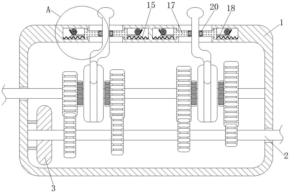
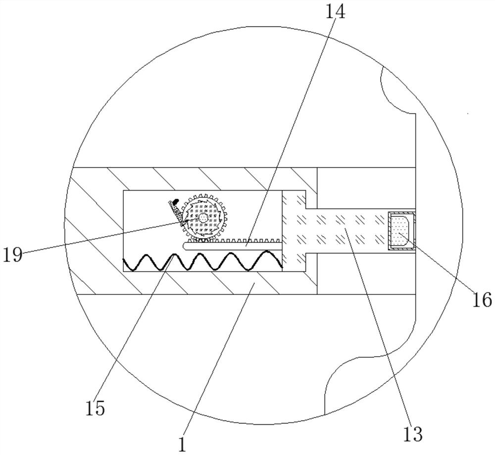
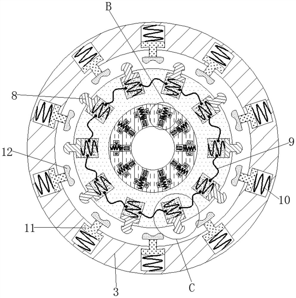
[0026] see Figure 1-5 , a belt conveyor speed regulating mechanism for an automated production line, comprising a box body 1, the inside of the box body 1 is movably connected to a power shaft 2, the outside of the power shaft 2 is fixedly connected to a casing 3, and the inside of the casing 3 is movably connected to an induction component 4. The induction component 4 is mainly composed of a sleeve, a socket rod, a counterweight, a copper rod, an N pole, an ...


PUM


Abstract

The invention relates to the technical field of automatic production lines, and discloses a belt conveyor speed regulating mechanism for an automatic production line. The belt conveyor speed regulating mechanism comprises a box body, wherein a power shaft is movably connected to the interior of the box body, a shell is fixedly connected to the exterior of the power shaft, sensing assemblies are movably connected to the interior of the shell, and limiting plates are movably connected to the interior of the shell; and an electrorheological body is movably connected into each limiting plate. Through the interaction among a rotating shaft, the induction assemblies, the limiting plates, electric wires, the electrorheological bodies, springs I, movable blocks, springs II, speed reducing plates and movable rods, the rotating shaft can be subjected to timely speed reducing treatment when the rotating speed of the rotating shaft exceeds a normal range, so that the situations that because the rotating speed of the rotating shaft is too high due to motor current overload or other reasons, a belt conveyor cannot work normally and the body of a worker is hurt are avoided, and the use of the belt conveyor better conforms to the actual situation.

Description

technical field [0001] The invention relates to the technical field of automation production lines, in particular to a belt conveyor speed regulating mechanism for an automatic production line. Background technique [0002] Belt conveyor is a kind of object conveying device, which has the advantages of large conveying capacity, simple structure, convenient maintenance, and standardized components. Therefore, it is widely used in the production fields of electronics and machinery, and can meet the production needs of automated production lines. [0003] During the operation of the belt conveyor, its transmission speed is controlled by the speed regulating mechanism. During the operation of the existing speed regulating mechanism, the current overload may cause the rotation speed of the motor shaft to be too fast or due to the operator The operation error caused the rotating speed of the rotating shaft to exceed the normal speed range of the belt conveyor, so that the conveyin...

Claims


Application Information

Patent Timeline
IPC IPC(8): B65G15/32B65G23/30
CPCB65G15/32B65G23/30
Inventor 董江海
Owner 深圳市华智信息科技有限公司
Why Eureka
Try Eureka