Sludge-blockage-preventing desliming machine for sewage treatment

A technology for sewage treatment and desliming machine, which is used in water/sludge/sewage treatment, water/sewage treatment, water/sewage treatment equipment, etc. Efficiency decline and other problems, to achieve the effect of saving kinetic energy consumption, reducing the use of power sources, and ensuring the dehydration effect

Inactive Publication Date: 2021-01-05
张雷昌
View PDF0 Cites 1 Cited by
  • Summary
  • Abstract
  • Description
  • Claims
  • Application Information

AI Technical Summary

Problems solved by technology

[0003] Sludge often needs to be dehydrated during treatment. At this time, a dehydrator is needed. The working principle of the dehydrator is to use a high-speed rotating centrifugal cylinder to remove the water in the sludge. However, there are many problems in modern dehydrators. Defects, such as the high viscosity of the sludge, the sludge is easy to block the dehydration hole of the dehydrator when the dehydrator is working, resulting in a decrease in dehydration efficiency, and at the same time, the centrifugal cylinder is prone to large vibrations when rotating at high speed, resulting in premature damage to the device. Reduced service life

Method used


Image

  • Sludge-blockage-preventing desliming machine for sewage treatment
  • Sludge-blockage-preventing desliming machine for sewage treatment
  • Sludge-blockage-preventing desliming machine for sewage treatment

Examples


Embodiment Construction

[0026] The following will clearly and completely describe the technical solutions in the embodiments of the present invention with reference to the accompanying drawings in the embodiments of the present invention. Obviously, the described embodiments are only some, not all, embodiments of the present invention.

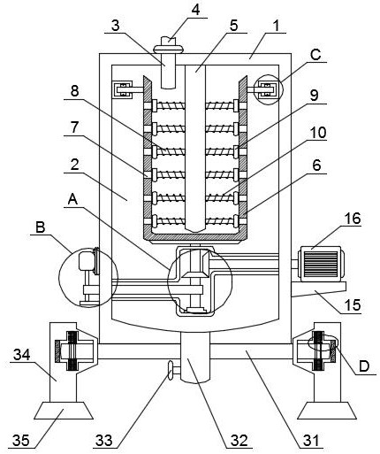
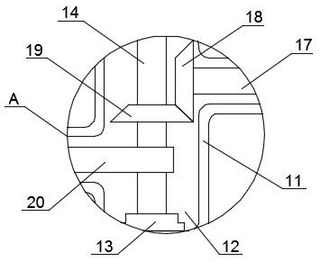
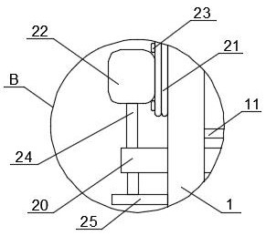
[0027] refer to Figure 1-5 , a desilter for sewage treatment to prevent silt clogging, comprising a shell 1, the outer bottom wall of the shell 1 is fixedly connected with a fixed base plate 31, and both ends of the fixed base plate 31 are provided with support columns 34, each support column 34 The bottom end of each is fixedly set with a shock absorber 35, and the two support columns 34 are all provided with a shock absorber 36, and the two shock absorber 36 are provided with a shock absorber, and the shock absorber includes a shock absorber located in the shock absorber. The fixed column 38 in the 36, the end of the fixed bottom plate 31 located in the damping gr...


PUM


Abstract

The present invention discloses a sludge-blockage-preventing desliming machine for sewage treatment, which comprises a shell, a fixed bottom plate is fixedly connected to the outer bottom wall of theshell, and supporting columns are arranged at the two ends of the fixed bottom plate in a sleeving mode. In the rapid dewatering process, the fixed shaft and the inner barrel rotate relatively, at themoment, the connecting rod and the spiral blade are matched to stir sludge in an overturning mode and scatter the sludge, the dewatering quality of the sludge is greatly improved, and along with rotation of the inner barrel, the sludge scraping plate continuously scrapes off the sludge on the inner side wall of the inner barrel. According to the sludge dewatering device, sludge is effectively prevented from being accumulated in the dewatering holes of the inner barrel to form blockage, and the sludge dewatering efficiency can be improved; meanwhile, the pressure springs and the fixing columnsare matched to damp the fixing bottom plate in the vertical direction, and the buffer pads buffer the fixing bottom plate in the horizontal direction; the two components are combined to release forceand buffer vibration generated by working of the desliming machine, damping of the desliming machine is achieved, and therefore stability of the desliming machine in the working process is guaranteed, and potential safety hazards are reduced.

Description

technical field [0001] The invention relates to the technical field of sewage treatment, in particular to a deslimer for sewage treatment which prevents sludge clogging. Background technique [0002] At present, with the continuous development of science and technology, production-oriented fields such as industry and coal mining have made rapid progress, followed by more and more sewage generated, and a large amount of sludge will be generated during the treatment of these sewage . Sewage treatment is the process of purifying sewage to meet the water quality requirements of being discharged into a certain water body or reused. In the process of sewage treatment, many harmful substances in sewage will be hidden in sludge and difficult to purify, so Sludge needs to be separated from sewage for separate treatment. [0003] Sludge often needs to be dehydrated during treatment. At this time, a dehydrator is needed. The working principle of the dehydrator is to use a high-speed ...

Claims


Application Information

Patent Timeline
Patent Type & Authority Applications(China)
IPC IPC(8): C02F1/38C02F11/127F16F15/04B08B9/087
CPCB08B9/0808C02F1/38C02F11/127C02F2201/002C02F2303/14F16F15/04
Inventor 张雷昌
Owner 张雷昌
Why Eureka
Try Eureka