Textile dust collecting device for textile workshop

A collection device and textile dust technology, which is applied in the field of textile dust collection devices for textile workshops, can solve the problems of limited dust removal range and reduce the overall dust removal effect of textile workshops, and achieve the effects of reducing production costs, increasing the range, and saving water resources

Inactive Publication Date: 2021-01-05
蒋秀兰
View PDF0 Cites 13 Cited by
  • Summary
  • Abstract
  • Description
  • Claims
  • Application Information

AI Technical Summary

Problems solved by technology

[0003] The textile machine will produce a lot of textile dust when it is working, so the textile machine needs to use a dust collection device when it is in use. The existing textile dust collection device can only remove dust in a fixed angle direction, and the dust removal range is limited, thereby reducing the impact on the textile. The overall dust removal effect of the workshop

Method used


Image

  • Textile dust collecting device for textile workshop
  • Textile dust collecting device for textile workshop
  • Textile dust collecting device for textile workshop

Examples


Embodiment 1

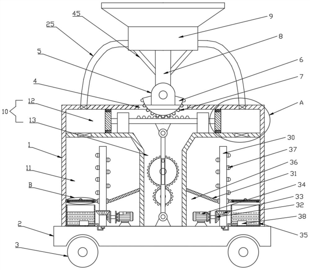
[0026] see Figure 1-6 , a textile dust collection device for a textile workshop, comprising a box body 1, the bottom surface of the box body 1 is provided with a base 2 and moving wheels 3 located at the four corners of the bottom surface of the base 2, and the top surface of the box body 1 is provided with a Hole 4, fixed block 5 is arranged symmetrically on both sides of described through hole 4, and described fixed block 5 is provided with rotating block 6 by pin shaft rotation, and the bottom surface of described rotating block 6 is arranged in through hole 4, and rotating block 6 The bottom surface is provided with gear teeth 7, and the top surface of the rotating block 6 is provided with a dust collection cover 9 through a connecting rod 8. The box body 1 is provided with a driving bin 10 and a dust collection bin 11, and the dust collection bin 11 is symmetrically arranged on On both sides of the drive chamber 10, the drive chamber 10 includes a horizontal chamber 12 a...

Embodiment 2

[0030] This embodiment has been improved on the basis of Embodiment 1, specifically:

[0031]Described dust collecting bin 11 is provided with dust-reducing mechanism, and described dust-reducing mechanism comprises rotating shaft 30, deflector 31, first helical gear 32, second helical gear 33, second motor 34 and water tank 35, and described dust-collecting bin 11. A sealed chamber 36 is provided through the deflector 31. A water tank 35 and a second motor 34 are respectively arranged on the left and right sides of the sealed chamber 36. The output end of the second motor 34 is connected with a first helical gear 32, so The bottom surface of the rotating shaft 30 is rotatably connected with the bottom surface of the dust collection bin 11 through bearings, and the second helical gear 33 meshing with the first helical gear 32 is sleeved on the rod body of the rotating shaft 30 located in the sealed bin 36, and the rotating shaft 30 is a hollow shaft , and the rotating shaft 30...


PUM


Abstract

The invention discloses a textile dust collecting device for a textile workshop. The textile dust collecting device comprises a box body, a driving bin and a dust removing bin are arranged in the boxbody, an angle adjusting mechanism and a negative pressure mechanism are arranged in the driving bin, and a dust falling mechanism is arranged in the dust removing bin. By arranging the angle adjusting mechanism, angle adjustment of a dust collecting cover is achieved, and the dust collecting range is enlarged; by arranging the negative pressure mechanism, a sliding rod drives a piston plate to reciprocate while reciprocating left and right, negative pressure is generated at a cover opening of the dust collecting cover through movement of the piston plate, dust collection is conducted on the surrounding environment through an air guide pipe, an induced draft fan does not need to be additionally arranged, and the production cost is reduced; textile dust sucked into the dust removing bin issubjected to efficient dust falling by arranging the dust falling mechanism; and impurities such as the dust and cotton fibers are filtered by arranging a filter screen, filtered clear water flows into a water tank again, cyclic utilization of water is achieved, and water resources are saved.

Description

technical field [0001] The invention relates to the technical field of textile equipment, in particular to a textile dust collection device for a textile workshop. Background technique [0002] Textile machines are also called spinning machines, looms and cotton spinning machines. The ancient textile machines are looms driven by manpower. Textile machine is exactly the full name of the tool that the raw material such as thread, silk and hemp is processed into silk thread and then weaves into cloth. Such as spinning pendants, spinning wheels, spindles and pedal looms, as well as modern mechanical looms and modern numerically controlled automatic looms. [0003] The textile machine will produce a lot of textile dust when it is working, so the textile machine needs to use a dust collection device when it is in use. The existing textile dust collection device can only remove dust in a fixed angle direction, and the dust removal range is limited, thereby reducing the impact on t...

Claims


Application Information

Patent Timeline
Patent Type & Authority Applications(China)
IPC IPC(8): D01H11/00D03J1/00D04B35/32B01D47/08B01D29/01B01D29/50
CPCB01D29/01B01D29/50B01D47/08B01D2247/04D01H11/005D03J1/002D04B35/32
Inventor 蒋秀兰
Owner 蒋秀兰
Why Eureka
Try Eureka