Heat dissipation device for automobile engine

A technology of automobile engine and heat dissipation device, which is applied in the direction of engine components, machine/engine, engine cooling, etc., can solve the problems of single heat dissipation structure and function of engine radiator, difficulty in releasing high-temperature air of engine, and affecting normal operation of engine, etc., to achieve Improve the effect of heat dissipation and cooling, accelerate air exchange, and improve the effect of heat dissipation

Inactive Publication Date: 2021-01-05
余华伟
View PDF0 Cites 3 Cited by
  • Summary
  • Abstract
  • Description
  • Claims
  • Application Information

AI Technical Summary

Problems solved by technology

[0003] The heat dissipation structure and function of the existing engine radiator are single, the high temperature air around the engine is difficult to release, and the heat dissipation effect is poor, which seriously affects the normal operation of the engine

Method used


Image

  • Heat dissipation device for automobile engine
  • Heat dissipation device for automobile engine
  • Heat dissipation device for automobile engine

Examples


Embodiment 1

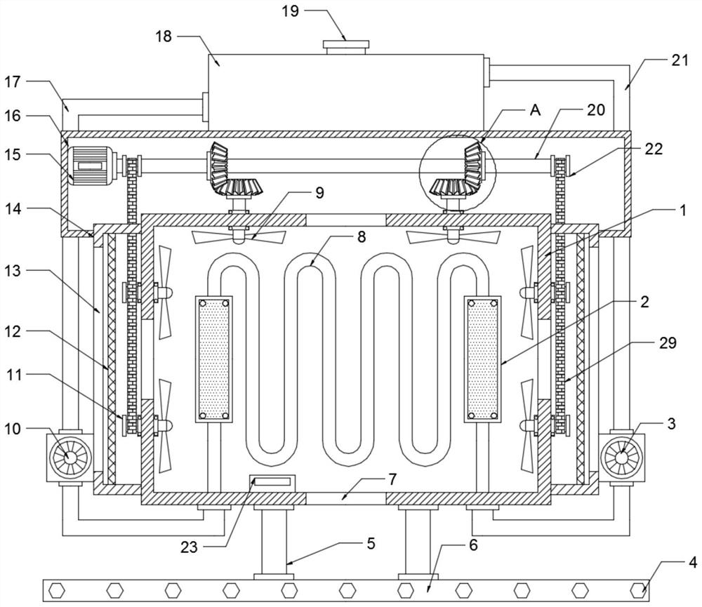
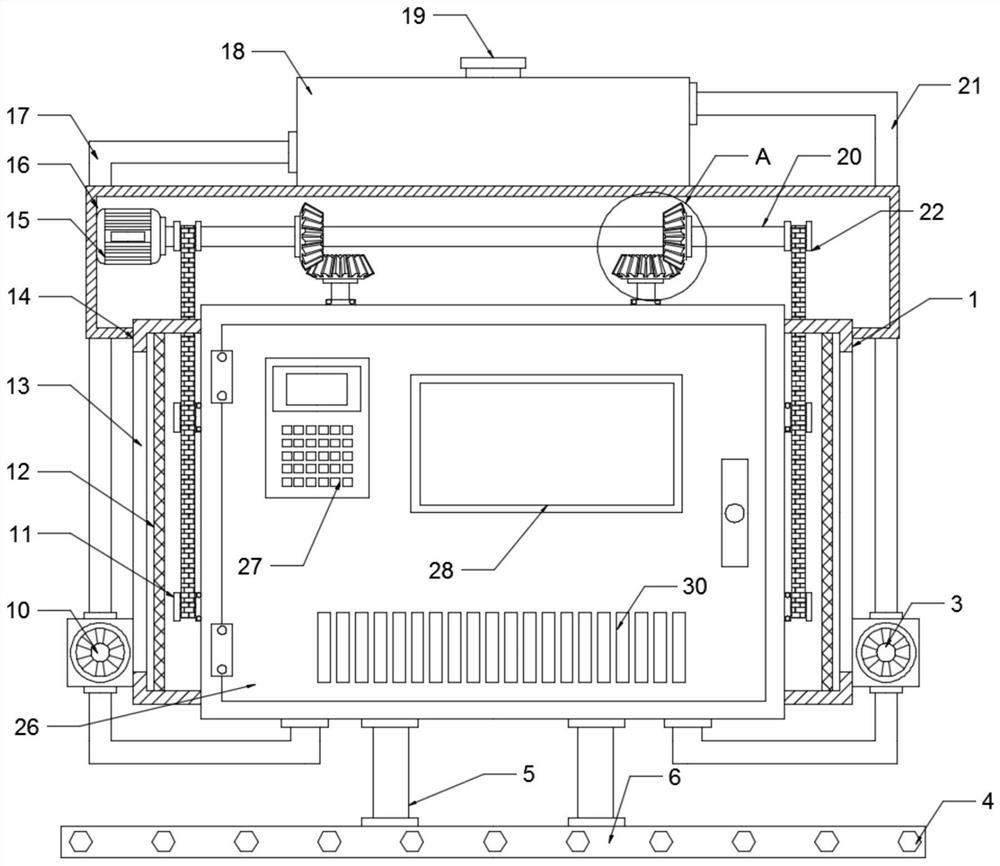
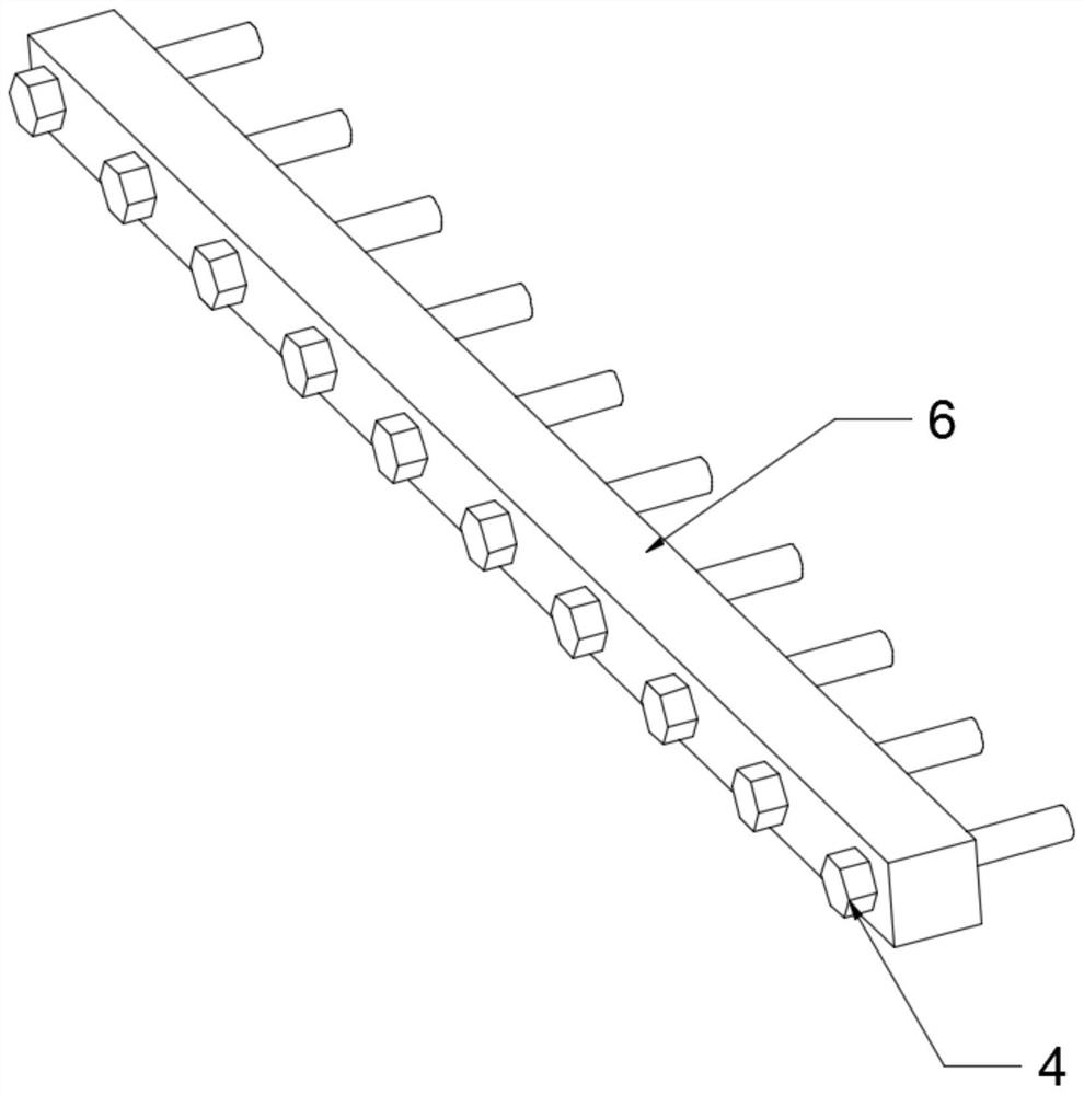
[0022] see Figure 1-4 , a heat dissipation device for an automobile engine, comprising a heat dissipation box 1 and a mounting base 6, an engine body is installed in the heat dissipation box 1, a heat dissipation port 7 is arranged in the middle of the side wall of the heat dissipation box 1, and the top wall of the heat dissipation box 1 A drive motor 15 is set, the output end of the drive motor 15 is fixedly connected to the rotating shaft 20, the left and right sides of the surface of the rotating shaft 20 are symmetrically provided with bevel gears 1-24, and the left and right sides of the inner top wall of the heat dissipation box 1 are symmetrically provided with fans 9. The fan 9 is rotatably connected with the top wall of the heat dissipation box 1, and the top of the fan 9 passes through the top wall of the heat dissipation box 1 through a connecting rod and extends and is fixedly connected to the second bevel gear 25. The second bevel gear 25 meshes with the bevel ge...

Embodiment 2

[0028] see Figure 1-2 , on the basis of Embodiment 1, in order to cool down the heat dissipation box 1, a water tank 18 is arranged above the heat dissipation box 1, and a water pump 10 is arranged on the left side of the heat dissipation box 1, and the water pump 10 and the water tank 18 pass through the water inlet pipe 17 connection, the serpentine cooling pipe 8 is set in the heat dissipation box 1, the water inlet pipe 17 extends through the left side wall of the heat dissipation box 1 and connects the serpentine cooling pipe 8, and the water pump 10 transfers the water in the water tank 18 through the water inlet pipe 17 The water is sent to the serpentine cooling pipe 8, and the serpentine cooling pipe 8 cools the inside of the heat dissipation tank 1. In order to repeatedly recycle the water in the water tank 18, a circulation pump 3 is arranged under the right side wall of the heat dissipation tank 1 The end of the serpentine cooling pipe 8 away from the water inlet ...


PUM


Abstract

The invention discloses a heat dissipation device for an automobile engine, and relates to the technical field of automobile auxiliary equipment. The heat dissipation device comprises a heat dissipation box and a mounting base, wherein an engine body is arranged in the heat dissipation box, and heat dissipation openings are formed in the middle portions of the side walls of the heat dissipation box; a driving motor is arranged above the top wall of the heat dissipation box, the output end of the driving motor is fixedly connected with a rotating shaft, and bevel gears I are symmetrically arranged on the left side and the right side of the surface of the rotating shaft; and a fan is arranged in the heat dissipation box, a water tank is arranged above the heat dissipation box, a water pump is arranged on the left side of the heat dissipation box and connected with the water tank through a water inlet pipe, and a coil cooling pipe is arranged in the heat dissipation box. The fan rotates to accelerate flow of air, the water pump conveys water in the water tank into the coil cooling pipe through the water inlet pipe, the coil cooling pipe cools the interior of the heat dissipation box,a circulating pump conveys the water in the coil cooling pipe into the water tank again through a water return pipe, and a water circulation cooling system is formed, so that water resources are saved, the heat dissipation and cooling effect on the engine is effectively improved, and normal operation of the engine is guaranteed.

Description

technical field [0001] The invention relates to the technical field of automobile auxiliary equipment, in particular to a radiator for an automobile engine. Background technique [0002] The car is an indispensable means of transportation. Among all the parts of the car, the engine is one of the most important parts of the car. In order to prevent the engine from overheating and stop the car from working, it is well known that the operating temperature of the engine is closely related to the power and fuel economy of the engine. Closely related, the radiator is an important part of it, and its main function is to increase the heat exchange area and prevent the engine from overheating. [0003] The heat dissipation structure and function of the existing engine radiator are single, the high-temperature air around the engine is difficult to release, and the heat dissipation effect is poor, which seriously affects the normal operation of the engine. Contents of the invention ...

Claims


Application Information

Patent Timeline
IPC IPC(8): F01P5/04F01P11/00F01P11/12
CPCF01P5/04F01P11/00F01P11/12F01P2005/046
Inventor 余华伟
Owner 余华伟
Why Eureka
Try Eureka