
Bearing running-in machine

A technology of bearings and spindles, which is applied in the direction of mechanical bearing testing, mechanical equipment, springs/shock absorbers, etc., can solve the problems that bearings of different sizes cannot be replaced, buffering and shock absorption cannot be provided, and bearing replacement is inconvenient, so as to improve quality, Solve the effect of inconvenient replacement of bearings and convenient replacement and fixation

Pending Publication Date: 2021-01-05
HUNAN MEIBEIDA TECH CO LTD
View PDF11 Cites 2 Cited by
  • Summary
  • Abstract
  • Description
  • Claims
  • Application Information

AI Technical Summary

Problems solved by technology

[0002] Bearing plays an important role in mechanical transmission, which reduces the friction in the power transmission process. As the requirements for bearings increase, it is necessary to run-in after bearing production. The use of bearing running-in machines improves the quality of bearing production; however, the existing patent CN103659149A runs There are disadvantages in the use of the fitting machine. It is impossible to replace the bearings of different sizes. The replacement of the bearing is inconvenient. At the same time, it cannot provide the function of cushioning and shock absorption.

Method used


Image

  • Bearing running-in machine
  • Bearing running-in machine
  • Bearing running-in machine

Examples


Embodiment 1

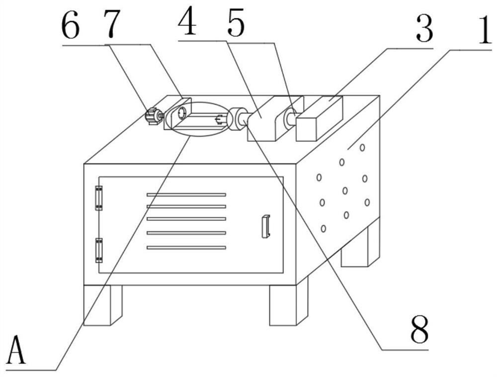
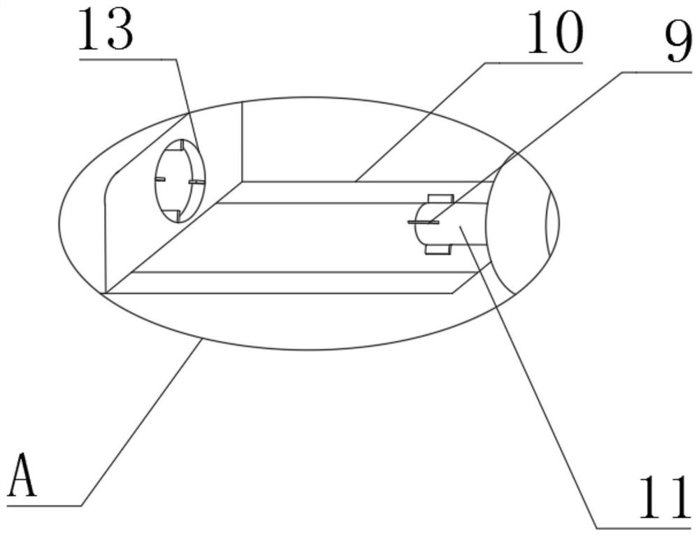
[0024] like figure 1 , 2 As shown, a bearing running-in machine includes a device main body 1, a gearbox 3 is arranged on the top surface of the device main body 1 near the right edge, a headstock 4 is arranged on the upper surface of the device main body 1 near the gearbox 3, and the main shaft A shaft coupling 5 is arranged between the case 4 and the gearbox 3, a main shaft 8 is arranged on the left side of the headstock 4, a rotating shaft 11 is arranged at the port of the main shaft 8, and a motor is arranged on the upper surface of the main body 1 near the left edge. 6. A fixed baffle 7 is arranged on the right side of the motor 6, and a threaded rod 16 is arranged between the fixed baffle 7 and the motor 6. The motor 6 drives the threaded rod 16 to rotate, and the fixed baffle 7 is moved and fixed by thread force.

[0025] A slide rail 10 is provided between the bottom of the fixed baffle 7 and the top surface of the main body 1 of the device. The slide rail 10 extends ...

Embodiment 2

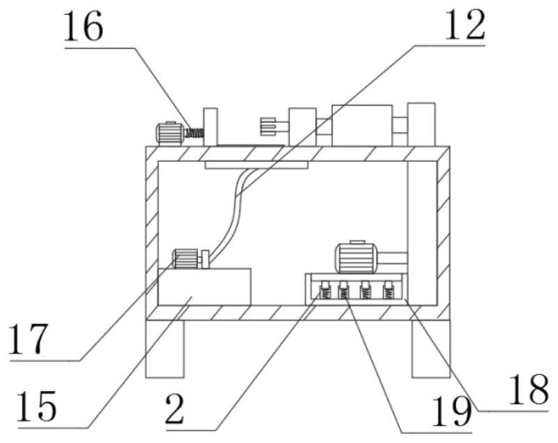
[0028] On the basis of Embodiment 1, such as image 3 , 4 As shown, the gearbox 3 runs through the top of the device main body 1 and is connected to the inner bottom surface of the device main body 1, and the inner bottom surface of the device main body 1 is provided with a shock absorbing plate 18 near the gearbox 3, and the inner bottom surface of the shock absorbing plate 18 is provided with a movable Groove 2, the interior of movable groove 2 is provided with damping spring 19, reduces the vibration of running-in machine, reduces noise and provides stable running-in environment, improves running-in quality.

[0029] The damping plate 18 and the device main body 1 are flexibly connected, the movable groove 2 and the damping plate 18 are fixedly connected, the damping spring 19 and the movable groove 2 are flexibly connected, and the number of movable grooves 2 is four groups. , the movable slots 2 are arranged in an array, and the number of shock absorbing springs 19 is fo...


PUM


Abstract

The invention discloses a bearing running-in machine. The bearing running-in machine comprises a device body, a gearbox is arranged at the position, close to the edge of the right side, of the surfaceof the top of the device body, a spindle box is arranged at the position, close to the gearbox, of the surface of the upper end of the device body, a shaft coupling is arranged between the spindle box and the gearbox, a spindle is arranged on the left side of the spindle box, a rotating shaft is arranged at the end opening of the main shaft, a motor is arranged at the position, close to the leftside edge, of the upper end surface of the device body, a fixed baffle is arranged on the right side of the motor, and a threaded rod is arranged between the fixed baffle and the motor. The bearing running-in machine has the good buffering and damping effects, the bearing running-in quality is improved, meanwhile, running-in can be conducted on bearings of different sizes, and the problem that thebearings are inconvenient to replace is solved.

Description

technical field [0001] The invention relates to the technical field of special equipment for bearings, in particular to a bearing running-in machine. Background technique [0002] Bearing plays an important role in mechanical transmission, which reduces the friction in the power transmission process. As the requirements for bearings increase, it is necessary to run-in after bearing production. The use of bearing running-in machines improves the quality of bearing production; however, the existing patent CN103659149A runs The running-in machine has disadvantages in the use process. It cannot replace the bearings of different sizes. The replacement of the bearing is inconvenient. At the same time, it cannot provide the function of cushioning and shock absorption. Therefore, we propose a bearing running-in machine. Contents of the invention [0003] The main purpose of the present invention is to provide a bearing running-in machine, which can effectively solve the problems i...

Claims


Application Information

Patent Timeline
Patent Type & Authority Applications(China)
IPC IPC(8): G01M13/04F16F15/04F16F15/067
CPCG01M13/04F16F15/04F16F15/067
Inventor 赵青华李治良梁泽显谢辉
Owner HUNAN MEIBEIDA TECH CO LTD
Learn More