Beam quality evaluation method based on vortex beam generated by fiber laser array

A vortex beam and fiber laser technology, applied in optics, optical components, instruments, etc., can solve the problems of inapplicability, difficulty in reflecting the mode purity, unsuitable beam quality evaluation method, etc., and achieve the effect of convenient application and mature measurement technology

Active Publication Date: 2022-02-08
NAT UNIV OF DEFENSE TECH
View PDF3 Cites 0 Cited by
  • Summary
  • Abstract
  • Description
  • Claims
  • Application Information

AI Technical Summary

Problems solved by technology

However, for the vortex beam produced by coherent combination of fiber laser array, the optical intensity on the axis is 0, and the light intensity distribution is ring-shaped. The mode purity is related to the helical phase structure of vortex beams, so BPF is not suitable as a beam quality evaluation method for vortex beams generated by fiber laser arrays

Method used


Image

  • Beam quality evaluation method based on vortex beam generated by fiber laser array
  • Beam quality evaluation method based on vortex beam generated by fiber laser array
  • Beam quality evaluation method based on vortex beam generated by fiber laser array

Examples


Embodiment 1

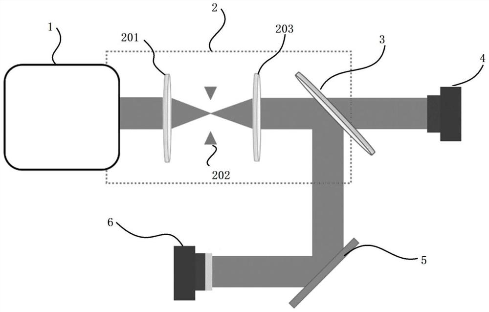
[0054] refer to figure 1 , the beam quality measurement system built for this embodiment can be used to measure some parameters that need to be used in the beam quality evaluation method based on the vortex beam generated by the fiber laser array.

[0055] like figure 1 As shown, the beam quality measurement system includes laser system 1, 4-f system 2, beam splitter 3, 1# optical power meter 4, spatial optical phase modulator 5 and 2# optical power meter for generating vortex beam by fiber laser array 6. 4-f system 2 includes 1# lens 201 , circular diaphragm 202 and 2# lens 203 . The laser system 1 that generates the vortex beam with the fiber laser array produces a vortex beam with a topological charge m that is spatially filtered by the 4-f system 2, and the output beam passes through the beam splitter 3, and the transmitted part of the beam is used to measure the vortex beam in the circular field Power ratio, reflected part of the beam is used to measure the power spectr...

Embodiment 2

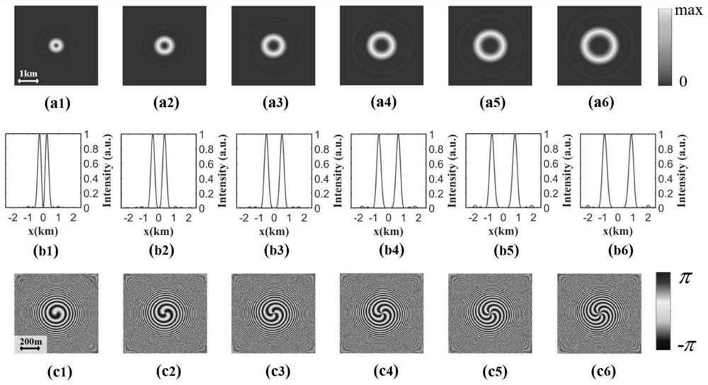
[0066] The second way to evaluate the beam quality of the target plane synthetic vortex beam, using numerical calculation, can be used for the optimal design of experimental system parameters. According to the numerical calculation to obtain the light intensity distribution I combined (ρ,ψ,,L), and then calculate the power ratio of the vortex beam in the circular domain.

[0067] Specifically, the beam quality evaluation method based on the fiber laser array to generate the vortex beam includes:

[0068] (1) Generate a vortex beam whose topological charge is m based on the fiber laser array, and obtain the light intensity distribution I of the synthetic vortex beam on the target plane at the distance z=L combined (ρ,ψ,L).

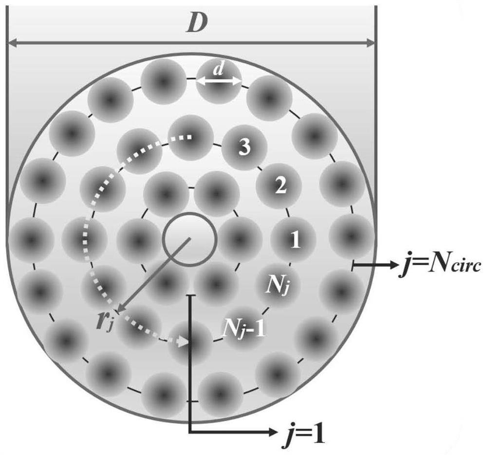
[0069] For a fiber laser array with a total aperture of D on the emitting surface, it is expected that the topological charge of the vortex beam generated is m, and the fiber laser array on the emitting surface is constructed as figure 2 As shown, its l...


PUM


Abstract

The beam quality evaluation method based on the vortex beam generated by the fiber laser array, the vortex beam whose topological charge is m is generated based on the fiber laser array, and the light intensity distribution of the target plane synthetic vortex beam at the distance z=L from the emission surface is obtained; The purity of the m-order orbital angular momentum mode in the circular domain of the synthetic vortex beam on the target plane at z=L from the emitting surface; calculate the high-order beam transmission factor; the closer the high-order beam transmission factor is to 1, the higher the topological charge based on the fiber laser array The beam quality of the vortex beam with the number m is better. The high-order beam transmission factor can effectively describe the energy concentration of the synthetic vortex beam, and considering the mode purity of the synthetic vortex beam, it can accurately evaluate the beam quality of the synthetic vortex beam.

Description

technical field [0001] The invention belongs to the technical field of fiber laser quality evaluation, and in particular relates to a beam quality evaluation method based on a fiber laser array generating vortex beams. Background technique [0002] Beam quality is an extremely important parameter in the application of laser technology and a performance index for evaluating laser characteristics. It is of great significance to guide the design, manufacture, detection and application of lasers and laser systems. Coherent combination of fiber laser array is one of the important methods to obtain high-brightness laser. It has broad application prospects in the fields of medical health, industrial processing, scientific research and national defense security. At present, there are many methods for coherent combination of fiber laser array to generate The beam quality of the beam is evaluated, such as M2 factor, Strehl ratio, power in the barrel, beam propagation factor (BPF), etc...

Claims


Application Information

Patent Timeline
Patent Type & Authority Patents(China)
IPC IPC(8): G02B27/00G02B27/09
CPCG02B27/0012G02B27/0994G02B27/0927
Inventor 周朴侯天悦马鹏飞马阎星粟荣涛吴坚李灿刘伟姜曼张雨秋常琦常洪祥王涛张嵩司磊许晓军陈金宝
Owner NAT UNIV OF DEFENSE TECH
Why Eureka
Try Eureka