
Projection screen

A projection screen and grating technology, which is applied in the field of projection screens, can solve the problems of energy waste and high brightness difference, and achieve the effects of good brightness uniformity, reduced optical and mechanical costs, and high gain

Active Publication Date: 2021-01-05
APPOTRONICS CORP LTD
View PDF13 Cites 1 Cited by
  • Summary
  • Abstract
  • Description
  • Claims
  • Application Information

AI Technical Summary

Problems solved by technology

Most of the light reflected by the surface Fresnel cannot enter the viewer's field of view, resulting in a waste of energy
At the same time, due to the uneven Fresnel reflection on the surface, the brightness difference between the center area and the edge area of ​​​​the screen surface is as high as 20%.

Method used


Image

  • Projection screen
  • Projection screen
  • Projection screen

Examples


Embodiment 1

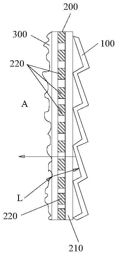
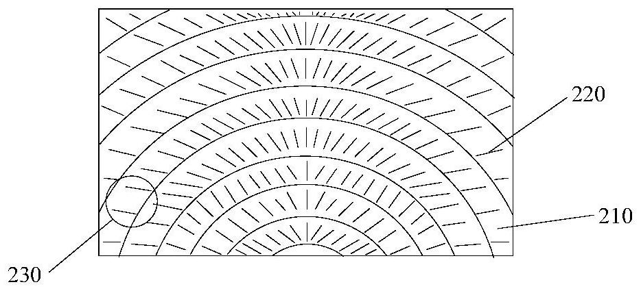
[0031] figure 1 It is a schematic diagram of a cross-sectional structure at the center of a projection screen according to Embodiment 1 of the present invention; figure 2 It is a schematic diagram of the grating setting position of the projection screen according to the embodiment of the present invention. Such as figure 1 and combine figure 2 As shown, the present invention provides a projection screen, with the viewer side as the outer side A, and the projection screen structure includes an optical alignment layer 100, a grating absorption layer 200, and a surface diffusion layer 300 from the inside to the outside, that is to say, on both sides Between the optical alignment layer 100 on the side and the surface diffusion layer 300 is a grating absorption layer 200 . The grating absorption layer 200 is used to absorb ambient light from all directions except the projected light direction, the optical collimation layer 100 is used to reflect the projected light, and the su...

Embodiment 2

[0042] Figure 4 It is a schematic structural diagram of the grating in Embodiment 2 of the present invention. Such as Figure 4 As shown, in this embodiment, the grating 220 disposed on the transparent substrate 210 has a trapezoidal cross section. The following combination Figure 4 Taking the trapezoidal grating as an example, the specific structure selection principle and size parameters of the grating of the present invention are described in detail.

[0043] Such as Figure 4 As shown, it shows two gratings 220 adjacent to the same concentric ring along the circumferential direction (arc direction), and gives the basic parameters of a grating:

[0044] L: the distance between two adjacent gratings (corresponding to the chord length on the concentric arc)

[0045] Wu: upper width of grating cross section

[0046] Wd: Lower width of grating cross section

[0047] d: the height of the raster

[0048] θ: Complete absorption angle, when the angle of incident light fro...

Embodiment 3

[0072] Figure 5 It is a schematic structural diagram of three gratings according to an embodiment of the present invention. Such as Figure 5 As shown, in this embodiment, the upper and lower widths of the cross section of the grating are equal, that is, when Wu=Wd, the grating is a cube and its cross section is a rectangle.


PUM

PropertyMeasurementUnit
Widthaaaaaaaaaa
Spacingaaaaaaaaaa

Abstract

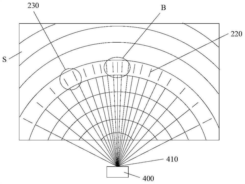
The invention provides a projection screen, which comprises an optical collimation layer and a surface diffusion layer which are arranged in sequence, and is characterized in that a grating absorptionlayer for absorbing ambient light from all directions except the projection light direction is also arranged between the optical collimation layer and the surface diffusion layer; the grating absorption layer comprises a plurality of light absorption annular units with different radiuses, the plurality of light absorption annular units are concentrically and annularly arranged, each light absorption annular unit is formed by arranging a plurality of gratings along the circumferential direction of a concentric ring, the light absorption annular units are arranged around the vertical symmetriccenter line of the projection screen, and the distance between every two adjacent gratings in the same light absorption annular unit is gradually increased in the direction in which the concentric rings extend towards the left side and the right side of the projection screen in the circumferential direction of the concentric rings. By arranging the gratings which are arranged in the concentric ring shape and are uneven in density, the projection screen has the advantages of being good in brightness uniformity and high in ambient light resistance.

Description

technical field [0001] The invention relates to a projection screen and belongs to the technical field of projection screen manufacturing. Background technique [0002] The screen is an important factor affecting the projection display system, and it has a great influence on the image quality of the projection display. The contrast of the picture reflected by the screen is affected by the ambient light and is much lower than the contrast of the projector itself. A typical projector screen can reflect both the light from the projector and the light from the ambient light. In order to improve the screen contrast in the presence of ambient light, the prior art includes anti-ambient light projection screens, such as: a wire grid screen is used in the patent CN1670618A, which improves the contrast of ambient light by absorbing light on one side and reflecting on the other. , but the gain of this type of screen is low; in the patent CN105408777A, Fresnel microstructure and light...

Claims


Application Information

Patent Timeline
IPC IPC(8): G03B21/56G03B21/60
CPCG03B21/56G03B21/60G03B21/602G03B21/625G03B21/58G03B21/62
Inventor 胡飞孙微王霖李屹
Owner APPOTRONICS CORP LTD
Learn More