Online measurement system for steam concentration of gas-phase mixture and method thereof

A steam concentration and measurement system technology, which is applied in the field of instrument measurement, can solve problems such as increasing the heat transfer resistance of condensation and affecting the heat transfer capacity of steam condensation, and achieve the effects of improving accuracy, easy deployment, and reducing mutual interference

Inactive Publication Date: 2021-01-05
NUCLEAR POWER INSTITUTE OF CHINA
View PDF11 Cites 0 Cited by
  • Summary
  • Abstract
  • Description
  • Claims
  • Application Information

AI Technical Summary

Problems solved by technology

Non-condensable gas has a great influence on the condensation characteristics of steam. Non-condensable gas gathers near the vapor-liquid interface, which increases the heat transfer resistance of condensation and greatly affects the heat transfer capacity of steam condensation.

Method used


Image

  • Online measurement system for steam concentration of gas-phase mixture and method thereof
  • Online measurement system for steam concentration of gas-phase mixture and method thereof

Examples


Embodiment 1

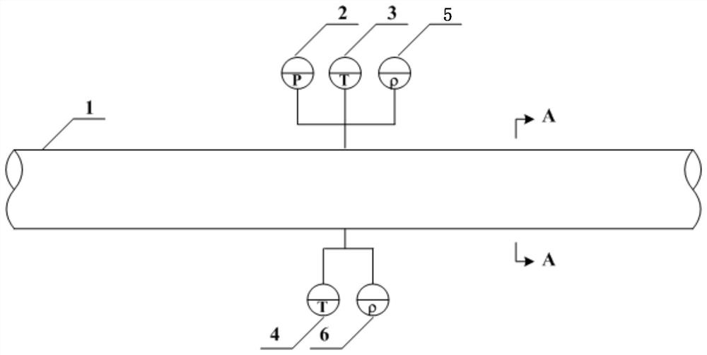
[0043] Such as figure 1 , figure 2 As shown, a vapor concentration online measurement system of a gas phase mixture includes a main gas pipe 1, a pressure sensor 2, a first temperature sensor 3, a second temperature sensor 4, a first density sensor 5 and a second density sensor 6;

[0044] The pressure sensor 2, the first temperature sensor 3, the second temperature sensor 4, the first density sensor 5 and the second density sensor 6 are installed on the side wall of the main air pipe 1; the pressure sensor 2, the first temperature sensor 3 , the second temperature sensor 4, the first density sensor 5 and the second density sensor 6 are arranged on the same axial plane of the main air pipe 1; the first density sensor 5 and the second density sensor 6 are tuning fork density meters.

[0045] The measurement method of the online measurement system described in this embodiment includes the following steps:

[0046] S1, through the pressure sensor 2, the first temperature senso...

Embodiment 2

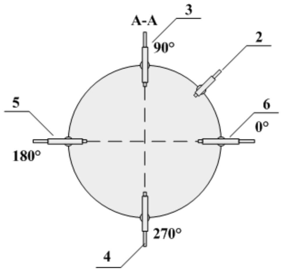
[0059] Such as figure 1 , figure 2 As shown, this embodiment is based on Embodiment 1, and the first temperature sensor 3 and the second temperature sensor 4 are arranged symmetrically with the central axis of the main air pipe 1; the first density sensor 5 and the second density sensor 6 are arranged with the main air pipe 1 The central axis of the trachea 1 is arranged symmetrically, specifically:

[0060] Take the horizontal point on the right side of the plane where the pressure sensor 2, the first temperature sensor 3, the second temperature sensor 4, the first density sensor 5 and the second density sensor 6 are located as 0°, and rotate counterclockwise; the pressure sensor 2 is located at 45° Orientation, the first density sensor 5 and the second density sensor 6 are located in the orientations of 0° and 180° respectively, and the first temperature sensor 3 and the second temperature sensor 4 are located in the orientations of 90° and 270° respectively.

Embodiment 3

[0062] Such as figure 1 , figure 2 As shown, this embodiment is based on Embodiment 1, the distance between the plane where the pressure sensor 2, the first temperature sensor 3, the second temperature sensor 4, the first density sensor 5 and the second density sensor 6 is located and the upstream straight pipe section is greater than or equal to 10 times The diameter of the main air pipe 1; the distance between the plane where the pressure sensor 2, the first temperature sensor 3, the second temperature sensor 4, the first density sensor 5 and the second density sensor 6 is located and the downstream straight pipe section is greater than or equal to 5 times the diameter of the main air pipe 1 .


PUM


Abstract

The invention discloses an online measurement system for the steam concentration of a gas-phase mixture and a method thereof. The online measurement system comprises a main gas pipe, a pressure sensor, a first temperature sensor, a second temperature sensor, a first density sensor and a second density sensor, the pressure sensor, the first temperature sensor, the second temperature sensor, the first density sensor and the second density sensor are installed on the side wall of the main gas pipe. The pressure sensor, the first temperature sensor, the second temperature sensor, the first densitysensor and the second density sensor are arranged on the same axial plane of the main air pipe. According to the method, the average temperature of the cross section is obtained through double-temperature measurement, the average density of the carrying surface is obtained through double-density measurement, the single-component density is obtained through pressure and temperature information, the steam concentration of steam mixing is obtained according to the relation between the single-component density and the average concentration of a mixture, and the method has the advantage of being high in accuracy.

Description

technical field [0001] The invention relates to the field of instrument measurement, in particular to an on-line measurement system and method for the vapor concentration of a gas phase mixture. Background technique [0002] When a reactor breach accident occurs, high-temperature and high-pressure fluid enters the containment vessel from the breach, and the upstream liquid flashes rapidly to form a large amount of steam, which is mixed with the air in the containment vessel to form a gas-phase mixture of steam and non-condensable gas. In order to prevent the pressure and temperature in the containment from exceeding the design limit, it is necessary to condense the steam in the gas phase mixture. Non-condensable gas has a great influence on the condensation characteristics of steam. Non-condensable gas gathers near the vapor-liquid interface, which increases the heat transfer resistance of condensation and greatly affects the heat transfer capacity of steam condensation. ...

Claims


Application Information

Patent Timeline
Patent Type & Authority Applications(China)
IPC IPC(8): G21C17/00G21C17/017G01N9/00G01N9/36
CPCG21C17/017G21C17/00G01N9/36G01N9/002G01N2009/006Y02E30/30
Inventor 臧金光张妍闫晓都宇胡强
Owner NUCLEAR POWER INSTITUTE OF CHINA
Why Eureka
Try Eureka