Laser pulse shaping device and method, pulse shaper, optical system

A pulse shaper and laser pulse technology, applied in the laser field, can solve the problems of poor accuracy and complicated operation, and achieve the effect of improving control error accuracy, enhancing use effect and improving accuracy

Active Publication Date: 2022-04-19
FEMTOSECOND RES CENT CO LTD
View PDF0 Cites 0 Cited by
  • Summary
  • Abstract
  • Description
  • Claims
  • Application Information

AI Technical Summary

Problems solved by technology

[0005] The purpose of this application is to solve one of the above-mentioned technical defects, especially the defects of complex operation and poor accuracy of re-testing and adjustment when the optical path of the equipment changes, and provide a laser pulse shaping device and method, pulse shaper, optical system

Method used


Image

  • Laser pulse shaping device and method, pulse shaper, optical system
  • Laser pulse shaping device and method, pulse shaper, optical system
  • Laser pulse shaping device and method, pulse shaper, optical system

Examples


Embodiment Construction

[0048] Embodiments of the present application are described in detail below, examples of which are shown in the drawings, wherein the same or similar reference numerals denote the same or similar elements or elements having the same or similar functions throughout. The embodiments described below by referring to the figures are exemplary only for explaining the present application, and are not construed as limiting the present application.

[0049] Those skilled in the art will understand that unless otherwise stated, the singular forms "a", "an", "said" and "the" used herein may also include plural forms. It should be further understood that the wording "comprising" used in the description of the present application refers to the existence of the stated features, integers, steps, and operations, but does not exclude the existence or addition of one or more other features, integers, steps, and operations.

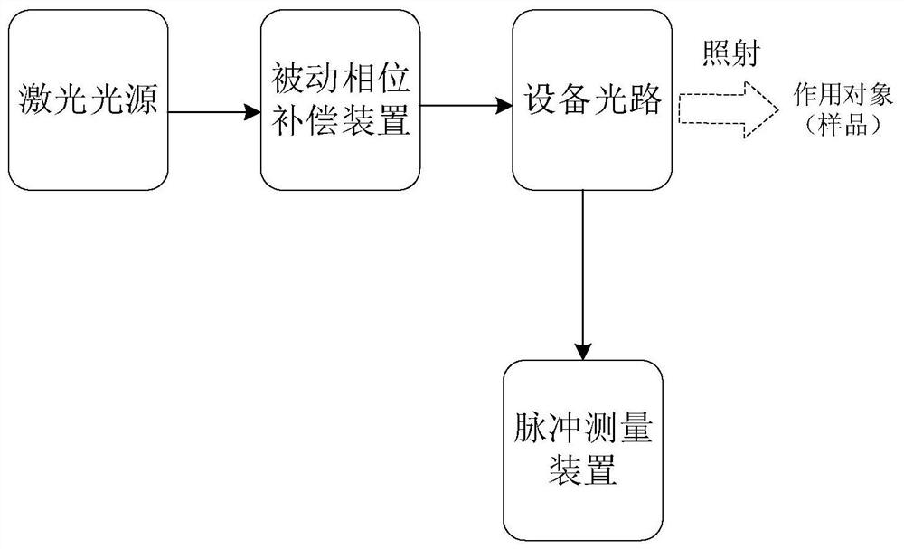
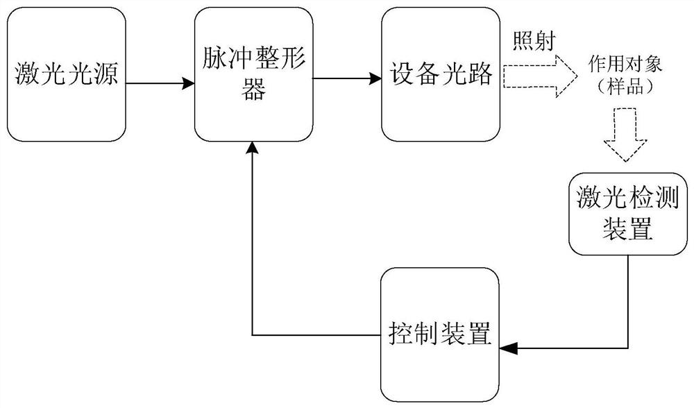
[0050] refer to figure 2 , figure 2 It is a structural schematic d...


PUM


Abstract

This application relates to a laser pulse shaping device and its method, pulse shaper, and optical system; the optical pulse shaping device includes: the pulse shaper is set on the optical path of the equipment connected to the laser light source, and the laser detection device is set on the actual object of the laser pulse position; the laser light source is used to generate laser pulses, which are transmitted through the optical path of the device and then emitted to the target; the laser detection device is used to measure the optical parameters of the laser pulses emitted to the target and send them to the control device The control device calculates the phase compensation parameter according to the optical parameter, and controls the pulse shaper to compensate the phase of the laser pulse passing through the optical path of the equipment according to the phase compensation parameter, so that the optical parameter of the laser pulse emitted to the object reaches the target value . This solution reduces the measurement complexity and can realize closed-loop testing. The pulse shaper can improve the accuracy of pulse compression compensation and enhance the effect of laser pulse use.

Description

technical field [0001] The present application relates to the field of laser technology, in particular to a laser pulse shaping device and method, a pulse shaper, and an optical system. Background technique [0002] In the laser pulse transmission process of the optical system, due to the dispersion in the optical path, especially the existence of second-order and higher-order dispersion, the laser pulse will produce a "time-domain broadening" effect when passing through the optical path, so that the laser pulse in the time axis The width on the time axis will increase with the propagation in the optical path, especially the femtosecond laser pulse. After the femtosecond laser pulse passes through the optical path, the width on the time axis even changes from femtosecond level to picosecond level. As a result, the peak power of the femtosecond laser pulse is greatly reduced, and the characteristics of the femtosecond laser pulse are lost. [0003] At present, optical system...

Claims


Application Information

Patent Timeline
Patent Type & Authority Patents(China)
IPC IPC(8): H01S3/00H01S5/00G02F1/133G02F1/1335
CPCH01S3/0057H01S5/0057G02F1/13318G02F1/133504G02F1/133526H01S2301/08H01S3/1305H01S3/1307H01S3/10069H01S3/0014H01S3/0085Y02P10/25G02B27/1006G02F1/137G02F2203/26
Inventor 徐炳蔚朱欣
Owner FEMTOSECOND RES CENT CO LTD
Why Eureka
Try Eureka