
Motor and electronic equipment with same

A motor and stator technology, applied in the field of motors and electronic equipment with motors, can solve the problems of reducing production manpower and cost, insufficient iron core flatness, multiple workmanship, etc., to reduce production manpower and cost, reduce bearing failure and damage, The effect of improving flatness

Active Publication Date: 2021-01-05
尼得科电机(东莞)有限公司
View PDF9 Cites 0 Cited by
  • Summary
  • Abstract
  • Description
  • Claims
  • Application Information

AI Technical Summary

Problems solved by technology

[0004] The present invention mainly solves technical problems such as lack of flatness of the motor iron core in the prior art, adding glue between the iron core and the bearing cavity for fixing, which consumes a lot of manpower and other technical problems, and proposes a motor and electronic equipment with the motor to ensure that most of the iron core Both are in contact with the matching part of the iron core of the bearing cavity to ensure higher fit strength and flatness of the iron core after pressing in; at the same time, reduce the glue coating process, reduce the number of man-hours and costs of production

Method used


Image

  • Motor and electronic equipment with same
  • Motor and electronic equipment with same
  • Motor and electronic equipment with same

Examples


Embodiment 1

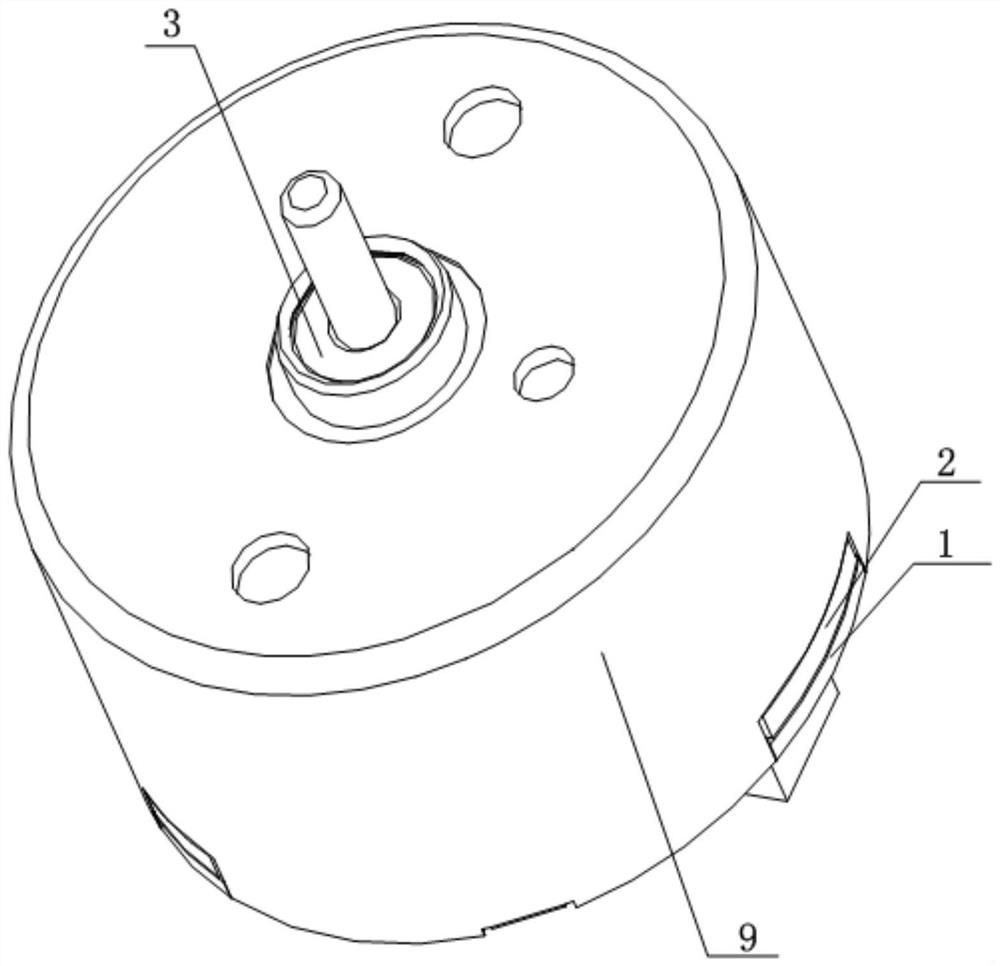
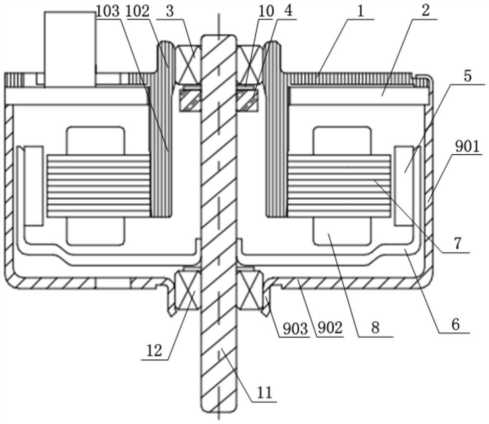
[0036] figure 1 It is a schematic structural diagram of the motor provided in Embodiment 1 of the present invention; figure 2 It is a sectional view of the motor provided by Embodiment 1 of the present invention. Such as figure 1 , 2 As shown, the motor provided by the embodiment of the present invention includes: a casing 9 and a stator and a rotor arranged in the casing 9 .

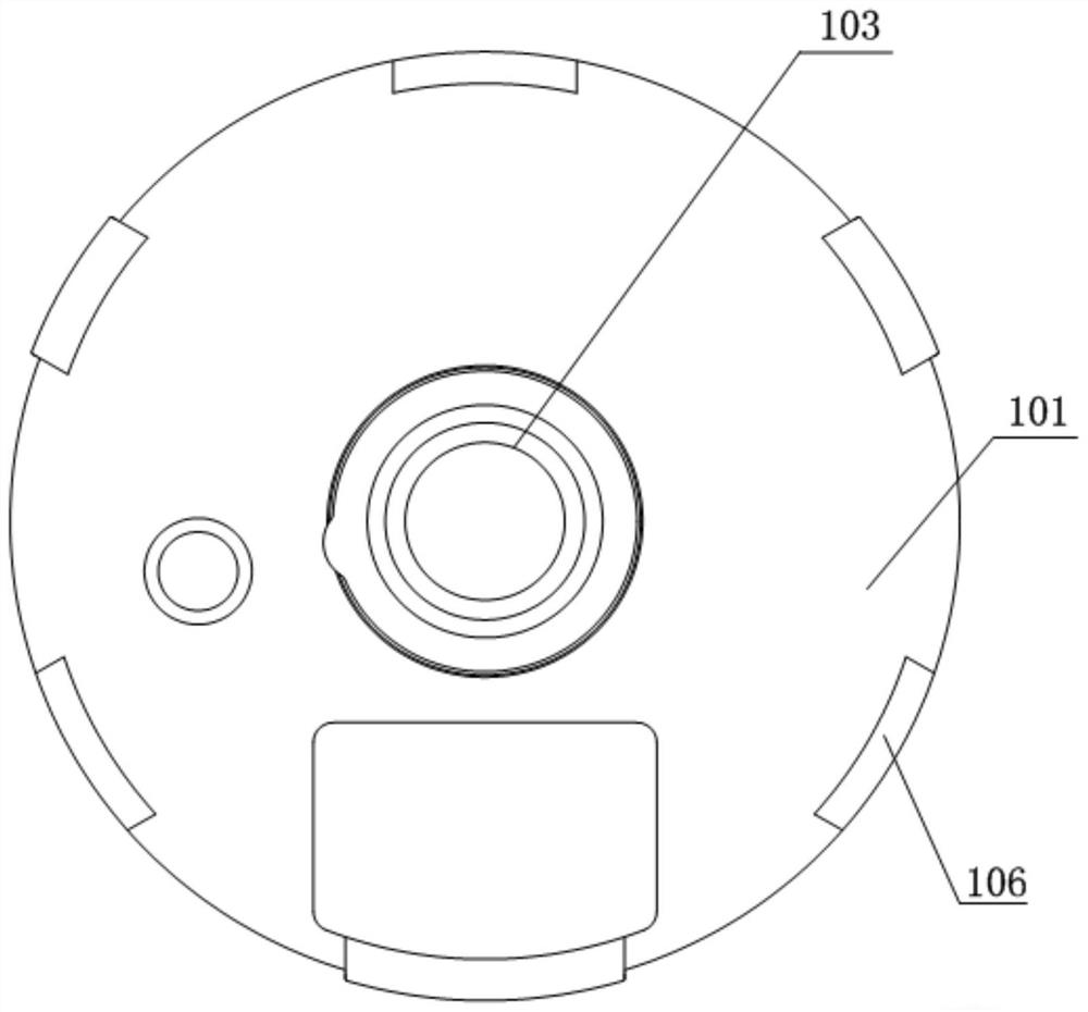
[0037] The motor type provided in this embodiment is an external rotor motor + a contact-proof casing. The stator includes: a stator core 7 , a coil 8 , a circuit board 2 and a bearing holder 1 ; the bearing holder 1 is fixed on a casing 9 . The stator core 7 and the coil 8 are arranged in cooperation, and the circuit board 2 is fixed on the inner side of the bearing holder 1 . The stator core 7 and the coil 8 are press-fitted with the bearing cage 1 for interference fit.

[0038] The rotor includes: a shaft 11 , a rotor frame 6 and a rotor magnet 5 . The shaft 11 passes through the casing 9 and...

Embodiment 2

[0045] This embodiment provides an electronic device, and the electronic device has the motor provided by any embodiment of the present invention. The electronic equipment includes, but is not limited to, refrigerators, washing machines, fans, air conditioners, clocks, and the like. The electronic equipment using the motor provided by any embodiment of the present invention can reduce the overall noise of the electronic equipment and prolong the service life.


PUM


Abstract

The invention relates to the technical field of motors, and provides a motor and electronic equipment with the motor, and the motor comprises a housing, and a stator and a rotor which are disposed inthe housing. The stator comprises a stator core, a coil, a circuit board and a bearing retainer. The bearing retainer is fixed on the shell; the rotor comprises a shaft, a rotor frame and a rotor magnet. The bearing retainer is provided with a disc-shaped base part, a first cylindrical part and a second cylindrical part, wherein the first cylindrical part and the second cylindrical part extend from the center of the base part along the two sides in the axial direction. A first bearing is accommodated in the first cylindrical part; a stator iron core is fixed at the periphery of the second cylindrical part; and the end part of the second cylindrical part is aligned with the axial end surface of the stator iron core or protrudes out of the axial end part of the stator iron core. According tothe invention, most of the iron core can be ensured to contact with the matching part of the iron core of the bearing cavity part, and higher matching strength and flatness after the iron core is pressed in are ensured; and meanwhile, the gluing process is reduced, and the number of production processes and cost are reduced.

Description

technical field [0001] The invention relates to the technical field of motors, in particular to a motor and electronic equipment with the motor. Background technique [0002] Motors are widely used in various electronic devices in daily work and life, such as refrigerators, washing machines, fans, air conditioners, clocks, etc. [0003] In the existing motor structure, the plane of the front side of the iron core is higher than the plane of the fixed part of the iron core in the bearing cavity; glue is added between the iron core and the bearing cavity to fix it; in this case, the flatness of the iron core will be insufficient. The copper wire produces an irregular magnetic field, which produces certain vibration and noise. Moreover, the gluing process also consumes more man-hours, which increases the production cost. In addition, during the riveting process of the casing and the bearing cage, when the riveting part of the casing is bent, they contact at right angles, whic...

Claims


Application Information

Patent Timeline
IPC IPC(8): H02K5/16H02K1/18
CPCH02K5/161H02K1/187
Inventor 郭佳杰钟亮张磊
Owner 尼得科电机(东莞)有限公司
Learn More