

A low power consumption correction circuit for output voltage and automatic correction method
A technology of outputting voltage and correcting circuit, which is applied to the conversion device of output power, the conversion of DC power input to DC power output, electrical components, etc., can solve the problem of high static power consumption, avoid unstable current output and reduce power consumption. , the effect of large application value
- Summary
- Abstract
- Description
- Claims
- Application Information
AI Technical Summary
Problems solved by technology
Method used
Image

Examples
Embodiment 1
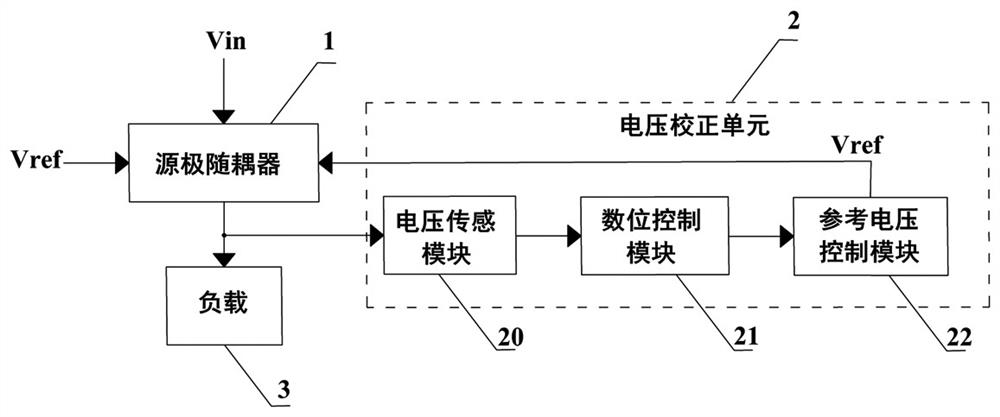
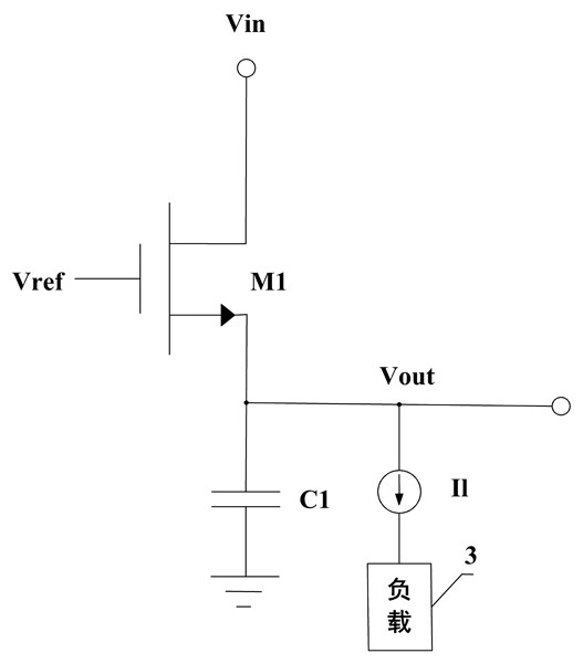
[0040] see figure 1 , the present invention provides an embodiment of an output voltage correction circuit with low power consumption, including a source follower 1 and a voltage correction unit 2 connected to the source follower 1 . Specifically, the voltage calibration unit 2 includes a voltage sensing module 20 , a digital control module 21 and a reference voltage control module 22 connected in sequence. The source follower 1 is connected to the voltage sensing module 20 and the reference voltage control module 22 . It should be noted that, in order to reduce power consumption, the system-on-a-chip using the linear voltage converter will enter the sleep standby mode when not transmitting data. There will be a quiescent current during this process, resulting in a certain quiescent power consumption. Using a source follower can effectively improve this technical problem. The source follower itself does not have quiescent current, and it is easy to operate at low voltage, but...
Embodiment 2
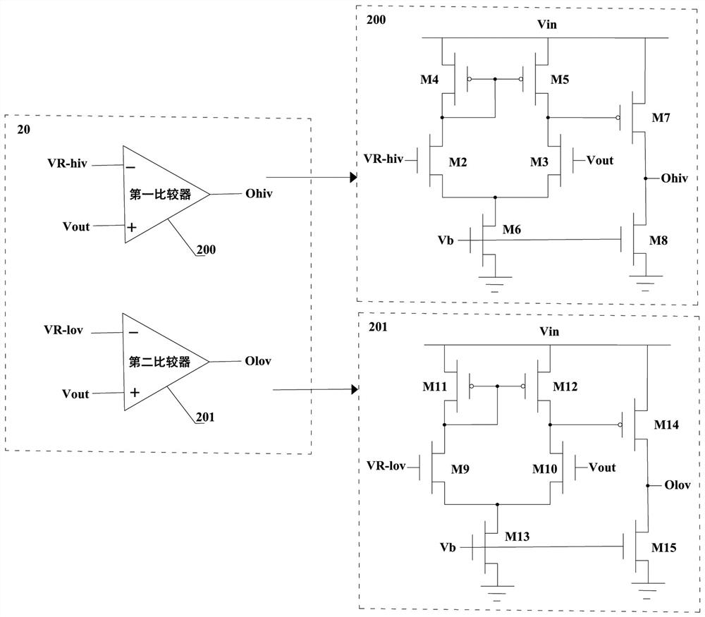
[0050] see Image 6 , the present invention also provides an embodiment of an automatic calibration method for output voltage, including the low power consumption calibration circuit described in Embodiment 1, wherein the voltage sensing module 20 includes a first comparator 200 and a second comparator 201, and the digital The control module 21 is provided with an oscillator, and the oscillator includes a D flip-flop and a multi-element ripple transfer adder. The steps of the automatic correction method of the present embodiment are as follows;
[0051] S1. Set a standard specification voltage and a preset ratio, and calculate a first target voltage and a second target voltage based on the standard specification voltage and the preset ratio. Specifically, the standard specification voltage is determined according to the load 3 connected to the low power consumption correction circuit, and the calculation formulas of the first target voltage and the second target voltage are r...
PUM
 Abstract
Description
Claims
Application Information