Rapid cleaning sand screening machine

A kind of sand screening machine, fast technology, applied in the field of sand screening machine, can solve the problems of inconvenient feeding, inability to carry out continuous sand screening operation, affecting sand screening efficiency, etc., and achieve the effect of small loss

Inactive Publication Date: 2021-01-08
胡峥
View PDF5 Cites 0 Cited by
  • Summary
  • Abstract
  • Description
  • Claims
  • Application Information

AI Technical Summary

Problems solved by technology

[0003] However, the existing construction sand screening machine is inconvenient to load materials, and cannot carry out continuous sand screening operations. It needs frequent cleaning of impurities, which affects the efficiency of sand screening.

Method used


Image

  • Rapid cleaning sand screening machine
  • Rapid cleaning sand screening machine
  • Rapid cleaning sand screening machine

Examples


Embodiment 1

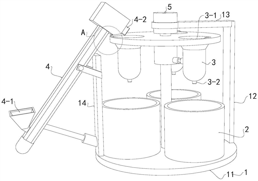
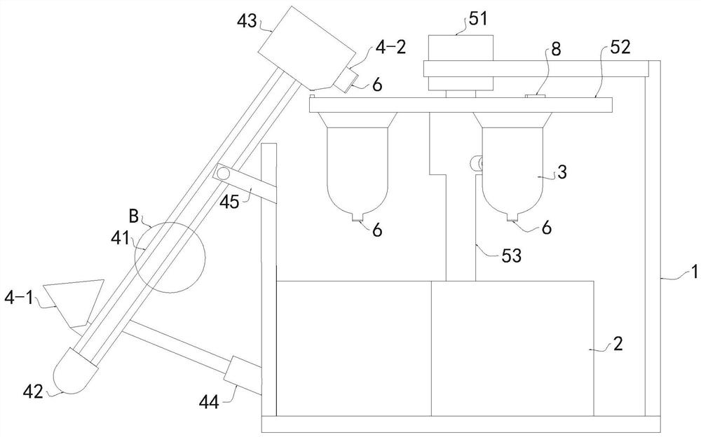
[0043] see Figure 1-12 , a quick-cleaning sand screening machine, comprising a frame 1, a material receiving box 2, a sand bag 3, a feeding assembly 4 and a sand screening system; the number of sand bags 3 is at least 2, and the sand bags 3 are equidistantly distributed inside the frame 1 , the upper and lower ends of the sand pocket 3 are respectively provided with a feed port 3-1 and a miscellaneous discharge port 3-2, the feed port 3-1 is used for sand feeding, and the miscellaneous discharge port 3-2 is used for discharge; the receiving box 2 Corresponding to the number of sand pockets 3, located below the sand pockets 3, and placed on the frame 1 in a circular manner, used to accept sand or impurities leaked from the miscellaneous discharge port 3-2; the feeding component 4 is installed on the frame 1 , used to add sand to the sand pocket 3, the two ends of the feeding assembly 4 are respectively provided with a sand inlet 4-1 and a sand outlet 4-2, the sand outlet 4-2 i...

Embodiment 2

[0055] see Figure 9 , different from Embodiment 1, the energization structure 541 includes a energization coil 54b, the energization coil 54b is installed in the column 53 and is close to the upper spline sleeve 544, and the middle sleeve 543 is inside the energization coil 54b, when the energization coil 54b is energized At this time, the middle sleeve 543 generates an attractive force and moves up to be inserted into the upper spline sleeve 544; when the electromagnet 54a1 is turned off, the attractive force disappears, and the middle sleeve 543 returns to its position under the action of gravity and is inserted into the lower spline Inside the sleeve 542.

[0056] When working, by energizing the energized coil 54b, the energized coil 54b has an upward suction force on the middle sleeve 543, so that the middle sleeve 543 is snapped into the upper spline sleeve 544. After the power is turned off, the middle sleeve 543 will Snap into the lower spline sleeve 542.


PUM


Abstract

The invention discloses a rapid cleaning sand screening machine, and belongs to the field of sand screening machines. The rapid cleaning sand screening machine comprises a machine frame, material receiving boxes, sand bags, a feeding assembly and a sand screening system. The at least two sand bags are distributed on the inner side of the machine frame at equal intervals, a feeding port and an impurity discharging port are formed in the two ends of each sand bag correspondingly, the feeding ports are used for feeding sand, and the impurity discharging ports are used for discharging materials. The material receiving boxes correspond to the sand bags in number, are located below the sand bags, are annularly placed on the machine frame and are used for receiving the sand or impurities leakingfrom the impurity discharging ports. The feeding assembly is installed on the machine frame and used for adding the sand into the sand bags, continuous operation of a series of operations of sand adding, sand loading, sand screening and impurity removing can be achieved, the sand screening efficiency is high, the impurity removing effect is good, a motor in the operation process can be effectivelyprotected, and the situation that the service life of the motor is shortened due to the fact that the motor is turned off when needed in the operation process is avoided; and in addition, the inclination angle of the feeding assembly can be adjusted, and residual materials in the feeding assembly can be discharged.

Description

technical field [0001] The invention relates to the field of sand screening machines, in particular to a quick-cleaning sand screening machine. Background technique [0002] In construction sites, sand is often used as a raw material, such as when building walls. However, when the sand is transported, it will be mixed with a lot of impurities. Therefore, it is necessary to filter the sand to improve the quality of construction. [0003] However, the existing construction sand screening machines are inconvenient to load materials and cannot perform continuous sand screening operations, requiring frequent cleaning of impurities, which affects the efficiency of sand screening. Therefore, for the above present situation, there is an urgent need to develop a small and quick cleaning sand screening machine to overcome the deficiencies in current practical applications. Contents of the invention [0004] In view of the problems existing in the prior art, the object of the presen...

Claims


Application Information

Patent Timeline
IPC IPC(8): B07B1/28B07B1/46B07B1/42B65G47/74
CPCB07B1/28B07B1/46B07B1/42B65G47/74
Inventor 胡峥
Owner 胡峥
Why Eureka
Try Eureka