Al technical title is built by PatSnap Al team. It summarizes the technical point description of the patent document.
An industrial robot, multi-functional technology, used in manufacturing tools, metal processing equipment, auxiliary devices, etc., can solve problems such as increased cost, wrong welding position, offset, etc.
Inactive Publication Date: 2021-01-08
陈春莉
View PDF0 Cites 0 Cited by
Summary
Abstract
Description
Claims
Application Information
AI Technical Summary
This helps you quickly interpret patents by identifying the three key elements:
Problems solved by technology
Method used
Benefits of technology
Problems solved by technology
[0004] The purpose of the present invention is to provide a multi-functional industrial robot to solve the problems in the a...
Method used
Image
Click on the blue label to locate the original text in one second.
Reading with bidirectional positioning of images and text.
Examples
Embodiment 1
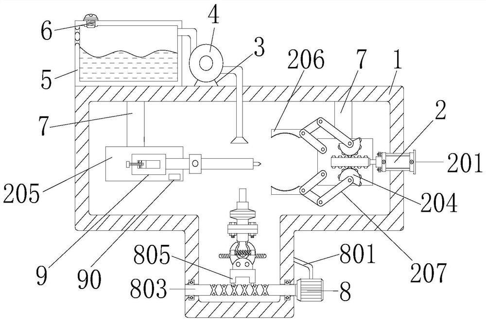
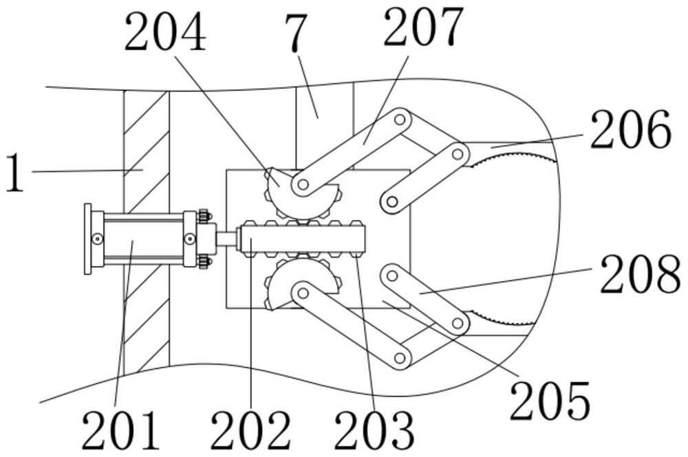
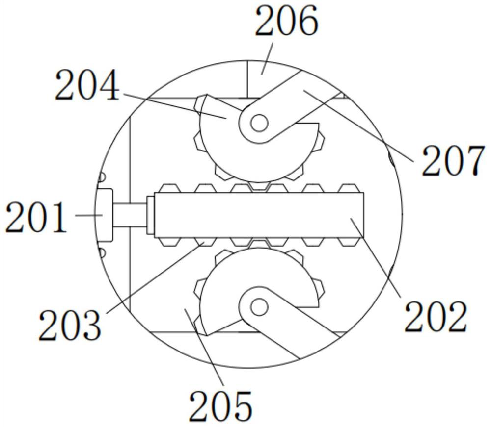
[0037]A multifunctional industrial robot, comprising a shell 1 and a vertical plate 7, two vertical plates 7 are fixedly connected to the left and right sides of the inner wall top of the shell 1, and a positioning device 2 is provided inside the shell 1, and the positioning device 2 includes a hydraulic cylinder 201 , horizontal plate 202, trapezoidal block 203, gear 204, thick plate 205, bent plate 206, first short plate 207 and second short plate 208, the model of hydraulic cylinder 201 is MOB, the outer wall of hydraulic cylinder 201 and the left side of shell 1 The side inner wall is fixedly connected, the internal hydraulic rod of the hydraulic cylinder 201 is fixedly connected with the left end of the horizontal plate 202, the upper and lower sides of the horizontal plate 202 are meshed with the inner walls of the two gears 204 through the trapezoidal block 203, and the horizontal plate 202 drives the trapezoidal block 203 During motion, just can drive gear 204 to rotate...
PUM
Abstract
The invention discloses a multifunctional industrial robot, comprising a shell and vertical plates, wherein the left side and the right side of the top of the inner wall of the shell are each fixedlyconnected to two vertical plates; a fixed device is arranged in the shell; the outer wall of a hydraulic cylinder is fixedly connected to the inner wall of the left side of the shell; a hydraulic rodin the hydraulic cylinder is fixedly connected to the left end of a transverse plate; right sides of the rear end faces of the two first short plates are rotationally connected to left sides of the front surfaces of two bent plates through pin shafts correspondingly, and left sides of the front surfaces of the two bent plates are rotationally connected to right sides of the rear end surfaces s oftwo third short plates through pin shafts correspondingly; and the left sides of the rear end surfaces of the two third short plates are vertically and rotationally connected to the right side of thefront surface of a thick plate through pin shafts. According to the multifunctional industrial robot disclosed by the invention, through cooperation of the bent plates, gears and trapezoidal blocks, the hydraulic cylinder indirectly drives the bent plates to rotate to clamp a workpiece for fixing, so that un-tight fixation and deviation are prevented, errors of a welding position are avoided, a weldment is prevented from becoming a waste piece, and cost is reduced.
Description
technical field [0001] The invention relates to the technical field of multifunctional industrial robots, in particular to a multifunctional industrial robot. Background technique [0002] There are many sources of energy for modern welding, including gas flames, arcs, lasers, electron beams, friction, and ultrasonic waves. In addition to being used in factories, welding can also be performed in a variety of environments, such as field, underwater, and space. Welding, wherever it occurs, can pose a hazard to the operator, so proper precautions must be taken when welding. [0003] However, the existing technology needs to be fixed manually when welding, and can only be fixed in the horizontal direction, which may lead to lax fixation, offset, lead to wrong welding positions, make welded parts become waste parts, increase costs, and The process of fixing in the prior art is cumbersome, wastes time, increases the labor force, and produces toxic gas during welding. The existing...
Claims
Application Information
Patent Timeline
Application Date:The date an application was filed.
Publication Date:The date a patent or application was officially published.
First Publication Date:The earliest publication date of a patent with the same application number.
Issue Date:Publication date of the patent grant document.
PCT Entry Date:The Entry date of PCT National Phase.
Estimated Expiry Date:The statutory expiry date of a patent right according to the Patent Law, and it is the longest term of protection that the patent right can achieve without the termination of the patent right due to other reasons(Term extension factor has been taken into account ).
Invalid Date:Actual expiry date is based on effective date or publication date of legal transaction data of invalid patent.