
Cutting machine for panel furniture production

A panel furniture, cutting machine technology, applied in the direction of manufacturing tools, forming/shaping machines, wood processing appliances, etc., can solve problems such as adverse effects on personal safety and health, consuming physical strength and time, and troublesome adjustment processes. The process is simple and fast, the movement is smooth, the effect of saving time and stamina

Inactive Publication Date: 2021-01-08
田佳豪
View PDF6 Cites 2 Cited by
  • Summary
  • Abstract
  • Description
  • Claims
  • Application Information

AI Technical Summary

Problems solved by technology

[0003] Aiming at the deficiencies of the prior art, the present invention provides a cutting machine for the production of panel furniture, which can cut out different sizes of wooden panels, and the operation is simple and fast; during the cutting process, no human hands are needed to push the panels, and the operation is safer , health advantages, solve the existing cutting machine, some can only be cut into wood boards of the same size, and some can be cut into wood boards of other sizes after adjustment, but the adjustment process is very troublesome and consumes a lot of physical strength and time , the efficiency is too low, and in the process of cutting, the operator needs to push the board slowly by hand. In the process, there are sparks and debris, which will adversely affect personal safety and health.

Method used


Image

  • Cutting machine for panel furniture production
  • Cutting machine for panel furniture production
  • Cutting machine for panel furniture production

Examples


Embodiment Construction

[0027] The technical solutions in the embodiments of the present invention will be clearly and completely described below with reference to the accompanying drawings in the embodiments of the present invention. Obviously, the described embodiments are only a part of the embodiments of the present invention, but not all of the embodiments. Based on the embodiments of the present invention, all other embodiments obtained by those of ordinary skill in the art without creative efforts shall fall within the protection scope of the present invention.

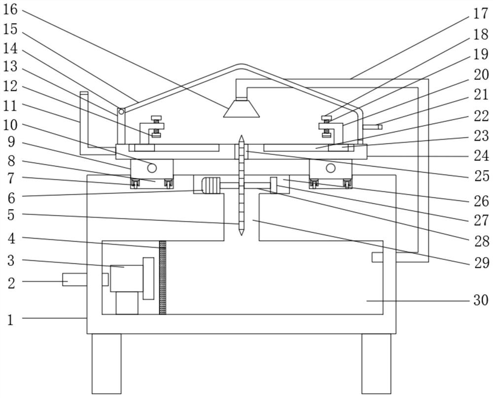
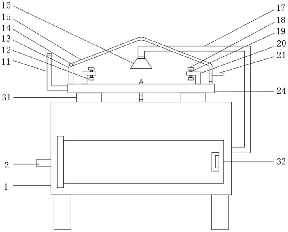
[0028] see Figure 1-6, a cutting machine for panel furniture production, comprising a base 1, the top of the base 1 is provided with a groove 26 and two first chutes 8, the inside of the base 1 is provided with a connection chamber 29 and a chip collection chamber 30, the chip collection chamber The longitudinal section of 30 is rectangular, and the length of the longitudinal section of the chip collecting chamber 30 is not less than...


PUM

PropertyMeasurementUnit
Diameteraaaaaaaaaa

Abstract

The invention relates to the technical field of cutting machines, and discloses a cutting machine for panel furniture production. The cutting machine comprises a base, a groove and two first sliding grooves are formed in the top of the base, a connecting cavity and a scrap collecting cavity are formed inside the base, the connecting cavity is located above the scrap collecting cavity, the scrap collecting cavity, the connecting cavity and the groove communicate with one another, and an exhaust fan is fixedly installed at the bottom of the scrap collecting cavity. Through arrangement of a second sliding groove and a rectangular cavity, when plates of different sizes need to be cut, only fixing bases need to be moved to clamp the plates between the two pairs of fixing bases, then the platesare fixed and cut by screwing rotating caps, time and physical strength can be greatly saved while it is guaranteed that the plates of different sizes can be cut, and through threaded connection of alead screw and a first sliding block, when two second motors are started, the first sliding block automatically slides along the lead screw to cut the plates, the plates do not need to be pushed by hands, and the safety of operators is improved.

Description

technical field [0001] The invention relates to the technical field of cutting machines, in particular to a cutting machine for panel furniture production. Background technique [0002] As a necessity in human life, furniture is the embodiment of people's life taste. Panel furniture is basically processed and manufactured from wood, and wood needs to be cut, polished, polished, etc. before it is made into panel furniture. The unique style of the furniture can only be displayed after fine treatment and processing. Among them, the cutting operation is also called the cutting operation, and the board is cut into the corresponding size according to the processing requirements. Cutting machine is an indispensable equipment in some light industries. It is suitable for processing various flexible sheet materials such as leather, cloth, textiles, plastics, rubber, cardboard, felt, asbestos, glass fiber, cork, and other synthetic materials. Applied to leather and shoemaking, handbag...

Claims


Application Information

Patent Timeline
IPC IPC(8): B27C5/02B27C5/06B27G3/00
CPCB27C5/02B27C5/06B27G3/00
Inventor 田佳豪
Owner 田佳豪
Learn More