Supercharge Your Innovation With Domain-Expert AI Agents!

Steel bar truss carrying mechanism

A steel truss and handling mechanism technology, which is applied to cranes, transportation and packaging, building construction, etc., can solve the problems of low production efficiency of steel truss floor decks, hidden safety hazards, and high labor intensity of operators, so as to reduce labor intensity And safety hazards, the effect of improving production efficiency

Pending Publication Date: 2021-01-08
TJK MACHINERY TIANJIN
View PDF0 Cites 2 Cited by
  • Summary
  • Abstract
  • Description
  • Claims
  • Application Information

AI Technical Summary

Problems solved by technology

At present, most of the handling of steel trusses is done by manpower. Manual handling of steel trusses will make the operator labor-intensive. Once the operator becomes fatigued, it will easily cause safety hazards.
Moreover, manual handling of steel trusses will result in low production efficiency of steel truss floor decks, which is not conducive to mass production of steel bar truss floor decks

Method used


Image

  • Steel bar truss carrying mechanism
  • Steel bar truss carrying mechanism
  • Steel bar truss carrying mechanism

Examples


Embodiment Construction

[0029] The present invention will be further described in detail below in conjunction with the accompanying drawings and embodiments. It should be understood that the specific embodiments described here are only used to explain the present invention, but not to limit the present invention. In addition, it should be noted that, for the convenience of description, only some structures related to the present invention are shown in the drawings but not all structures.

[0030] In the description of the present invention, unless otherwise clearly specified and limited, the terms "connected", "connected" and "fixed" should be understood in a broad sense, for example, it can be a fixed connection, a detachable connection, or an integrated ; It can be a mechanical connection or an electrical connection; it can be a direct connection or an indirect connection through an intermediary, and it can be the internal communication of two components or the interaction relationship between two ...


PUM


Abstract

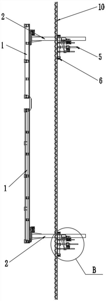
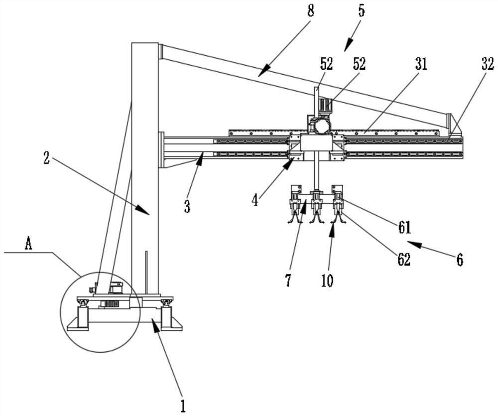
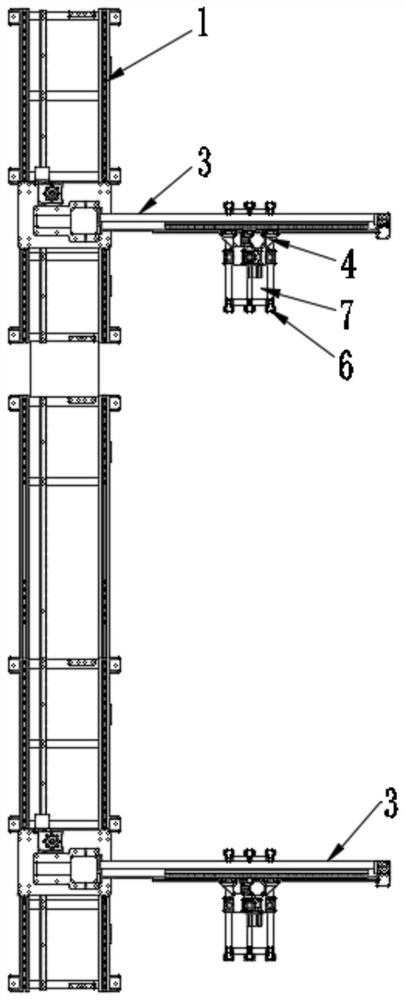
The invention belongs to the technical field of steel bar truss floor support plate production, and discloses a steel bar truss carrying mechanism which comprises a carrying base, a carrying rack mounted on the carrying base in a sliding manner, a fixed frame fixedly installed on the carrying rack in the first direction, a movable frame arranged on the fixed frame in a sliding manner in the firstdirection and a clamping jaw assembly; the first direction is perpendicular to the height direction of the carrying rack and the length direction of the carrying base; the clamping jaw assembly comprises a clamping jaw driving piece installed on the movable frame and a clamping piece driven by the clamping jaw driving piece to move in the second direction, the clamping piece is configured to clampa steel bar truss, and the second direction is consistent with the height direction of the carrying rack. According to the steel bar truss carrying mechanism, the clamping jaw assembly is used for clamping the steel bar truss, the movable frame slides along the fixed frame, clamping and automatic carrying of the steel bar truss can be achieved, the labor intensity and potential safety hazards ofoperators are reduced, and the production efficiency is improved.

Description

technical field [0001] The invention relates to the technical field of steel truss floor deck production, in particular to a steel truss handling mechanism. Background technique [0002] The steel truss floor deck belongs to a kind of unsupported pressure-type composite floor deck, which includes the bottom plate and the steel truss welded on the bottom plate. The steel truss mainly includes upper chord steel bars, lower chord steel bars and web bar steel bars. Steel trusses. [0003] Before the steel truss floor deck is welded, it is necessary to transport multiple steel trusses to the welding position, and then weld the multiple steel trusses to the bottom plate. At present, most of the handling of steel trusses is done by manpower. Manual handling of steel trusses will make the operator labor intensive, and once the operator becomes fatigued, it will easily cause safety hazards. Moreover, manual handling of the steel bar truss will result in low production efficiency of...

Claims


Application Information

Patent Timeline
Patent Type & Authority Applications(China)
IPC IPC(8): B66C23/00B66C1/44B66C13/18E04G21/16
CPCB66C23/00B66C1/44B66C13/18E04G21/162B66C2700/03
Inventor 陈振东其他发明人请求不公开姓名
Owner TJK MACHINERY TIANJIN
Features
  • R&D
  • Intellectual Property
  • Life Sciences
  • Materials
  • Tech Scout
  • Unparalleled Data Quality
  • Higher Quality Content
  • 60% Fewer Hallucinations
Learn More