Split type forklift overhead guard

A roof guard, split-type technology, applied to the roof, vehicle parts, lifting devices, etc., to achieve the effect of improving convenience, convenient arrangement and storage, and reducing weight

Inactive Publication Date: 2021-01-08
湖南川田机械制造有限公司
View PDF13 Cites 1 Cited by
  • Summary
  • Abstract
  • Description
  • Claims
  • Application Information

AI Technical Summary

Problems solved by technology

[0005] Aiming at the deficiencies of the prior art, the present invention provides a split-type forklift roof guard, which solves the problem that the existing roof guard and the forklift have an integrated structure, which requires the use of specific equipment and hoisting tools to adjust the height of the forklift roof question

Method used


Image

  • Split type forklift overhead guard
  • Split type forklift overhead guard
  • Split type forklift overhead guard

Examples


Embodiment 1

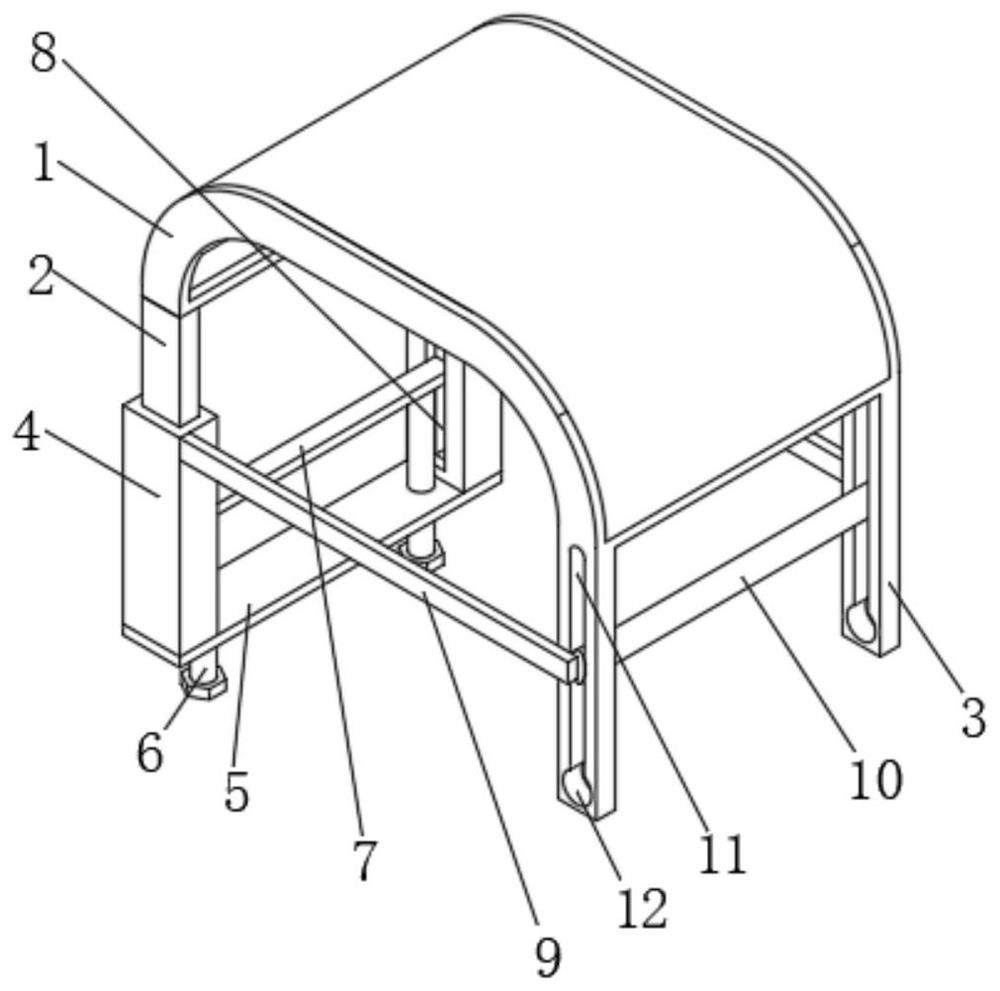
[0024] see Figure 1-2 , the present invention provides a technical solution: a split-type forklift roof guard, including an upper roof frame 1, the front side of the bottom of the upper roof frame 1 is fixedly connected with the tops of two groups of short slide bars 2, and the bottom of the upper roof frame 1 The rear sides of the two sets of long slide bars 3 are respectively fixedly connected to the tops, the outer side walls of the short slide bars 2 are slidably connected to the middle part of the slide seat 4, and the opposite sides of the two sets of slide seats 4 are provided with escape grooves 8. The avoidance groove 8 is passed through by the left side and the right side of the push plate 7 respectively, and the tops of the push plate 7 are in contact with the bottoms of the two groups of short slide rods 2 respectively, and the bottoms of the push plate 7 are respectively connected with the tops of the two groups of threaded rods 6 contact, the outer surfaces of t...

Embodiment 2

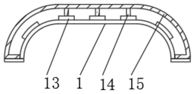
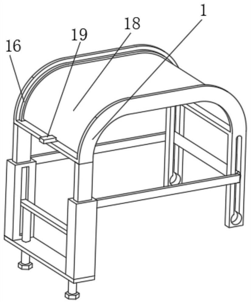
[0030] see Figure 2-4, the present invention provides a technical solution: a split-type forklift roof guard, including an upper roof frame 1, the front side of the bottom of the upper roof frame 1 is fixedly connected with the tops of two groups of short slide bars 2, and the bottom of the upper roof frame 1 The rear sides of the two sets of long slide bars 3 are respectively fixedly connected to the tops, the outer side walls of the short slide bars 2 are slidably connected to the middle part of the slide seat 4, and the opposite sides of the two sets of slide seats 4 are provided with escape grooves 8. The avoidance groove 8 is passed through by the left side and the right side of the push plate 7 respectively, and the tops of the push plate 7 are in contact with the bottoms of the two groups of short slide rods 2 respectively, and the bottoms of the push plate 7 are respectively connected with the tops of the two groups of threaded rods 6 contact, the outer surfaces of th...


PUM


Abstract

The invention relates to the technical field of forklift parts, and discloses a split type forklift overhead guard. The split type forklift overhead guard comprises an upper overhead guard body, the front side of the bottom of the upper overhead guard body is fixedly connected with the tops of two sets of short sliding rods, the rear side of the bottom of the upper overhead guard body is fixedly connected with the tops of two sets of long sliding rods, the outer side walls of the short sliding rods are slidably connected with the middles of sliding seats, and receding grooves are formed in theopposite sides of the two sets of sliding seats. According to the split type forklift overhead guard, two sets of threaded rods are screwed downwards, then push plates slide downwards along the receding grooves, meanwhile, the upper overhead guard body and the two sets of short sliding rods at the bottom of the upper overhead guard body slide downwards along the sliding seats, and therefore the height of the upper overhead guard body is reduced, the height of the forklift overhead guard can be adjusted conveniently, through matching of positioning rods, rectangular grooves and circular grooves, the upper overhead guard body can be opened, the height of the upper overhead guard body can be lowered more, the use convenience of the forklift overhead guard is improved, and a forklift can easily pass through a height limiting area.

Description

technical field [0001] The invention relates to the technical field of forklift parts, in particular to a split type forklift roof guard. Background technique [0002] Forklifts are an important handling tool in the logistics industry and are widely used in ports, docks, stations and various storage warehouses. The environment greatly restricts the use of forklifts. During loading and unloading operations, it is often encountered that the height of the forklift is too high to reach the designated work site, and the height of the forklift is affected by the tonnage of the vehicle, the height of the driver's seat and the height of the overhead guard. Combined impact. As an important safety part of forklift, the overhead guard is an indispensable part. In the design standard of forklift, there are clear requirements for the driver's head space, and the height of the overhead guard cannot be lowered casually, which leads to the need for the forklift to pass In places with heig...

Claims


Application Information

Patent Timeline
Patent Type & Authority Applications(China)
IPC IPC(8): B66F9/075B60J7/08
CPCB60J7/08B66F9/075B66F9/07545
Inventor 李强峰邱勇春李鑫曾武
Owner 湖南川田机械制造有限公司
Why Eureka
Try Eureka