Drainage pressure reduction device for centrifugal pump

A technology of decompression device and centrifugal pump, which is applied in the components, pump, pump control and other directions of the pumping device for elastic fluid, can solve the problems of low decompression efficiency, affect work efficiency, and cannot be graded decompression, and achieves Ensure the economic benefits of work, improve work efficiency, and ensure the effect of work efficiency

Inactive Publication Date: 2021-01-08
台州仁青泵业有限公司
6 Cites 0 Cited by

AI-Extracted Technical Summary

Problems solved by technology

[0003] For the water pump in the working process, when the water body pressure in the pump body exceeds the safe use limit value of the pump body, it needs to be controlled for decompression. On the one hand, the decompression measures for the pump body in the prior art have low decompression efficiency and are not effective. The pressure in the pump body can be decompressed in time. On the other hand, the discharge and decompression of the pump body cannot be decompressed in stages according to the actual...

Abstract

The invention discloses a drainage pressure reduction device for a centrifugal pump. When pressure reduction work is conducted on the centrifugal pump, drainage pressure reduction can be well conducted on the centrifugal pump through the drainage pressure reduction device. Drainage work is conducted according to the actual internal pressure condition of a pump body, and then normal work of the centrifugal pump is guaranteed. Through the arrangement of drainage bodies, pressure limiting springs and pressure reduction staged drainage mechanisms, staged drainage pressure reduction can be conducted on the centrifugal pump. When the internal pressure of the centrifugal pump body is too large, multi-stage drainage can be conducted according to the actual situation of the centrifugal pump body, and then the working efficiency of pressure reduction of the centrifugal pump body can be improved. The internal pressure of the pump body can be quickly recovered to be within a pressure safety use limit value, normal operation of the centrifugal pump is guaranteed, the working efficiency is guaranteed, damage to the centrifugal pump is avoided, and the working economic benefit is guaranteed.

Application Domain

Technology Topic

Image

  • Drainage pressure reduction device for centrifugal pump
  • Drainage pressure reduction device for centrifugal pump
  • Drainage pressure reduction device for centrifugal pump

Examples

  • Experimental program(1)

Example Embodiment

[0023]The technical solutions in the embodiments of the present invention will be described clearly and completely below. The embodiments of the present invention, and all other embodiments obtained by those of ordinary skill in the art without creative work, fall within the protection scope of the present invention.
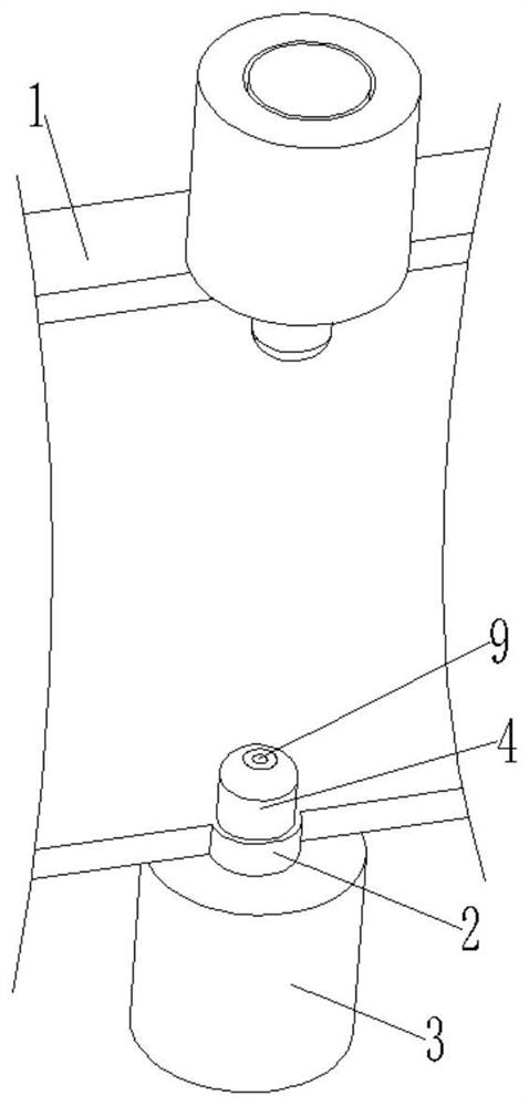
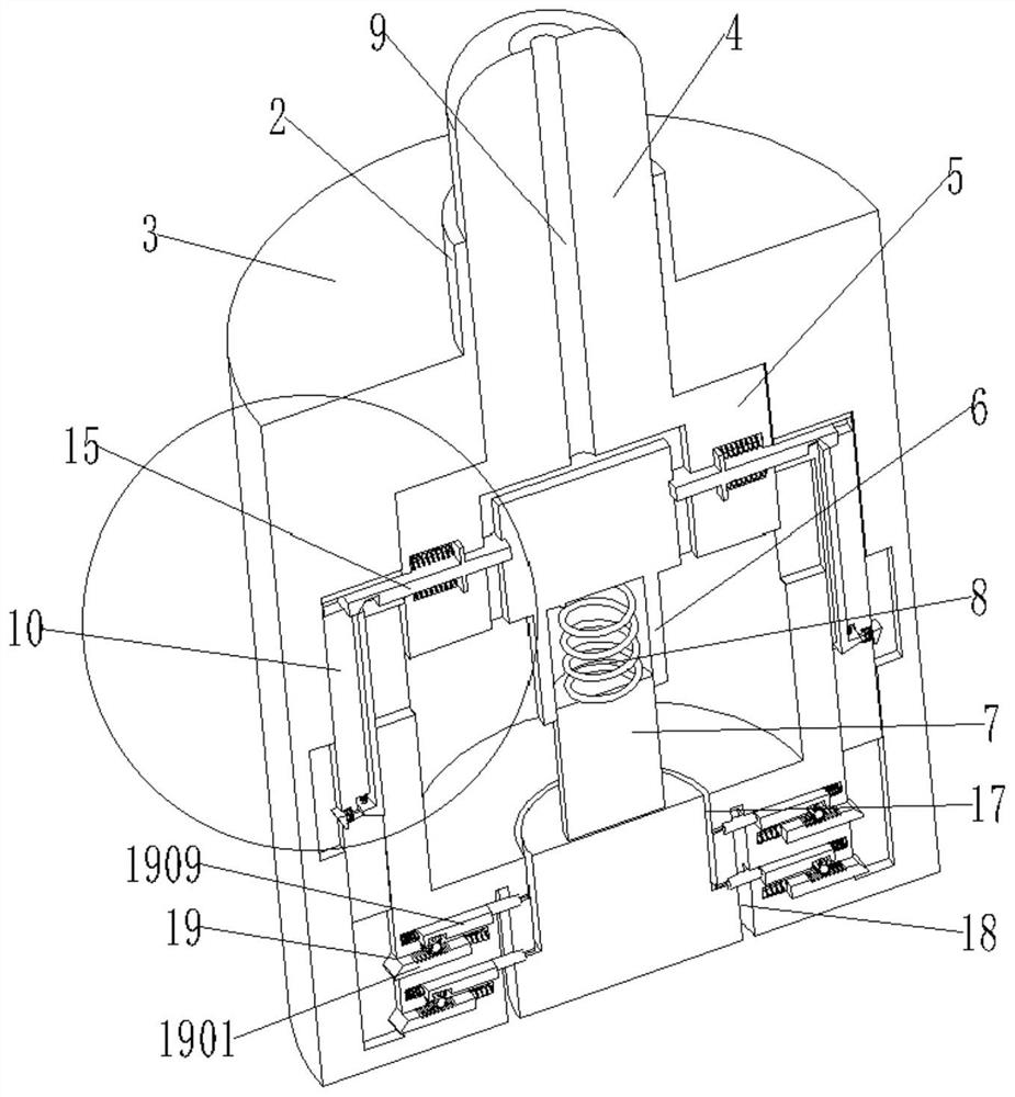
[0024]Please refer to the pictureFigure 1 to Figure 5, The present invention provides a technical solution: a centrifugal pump discharge and pressure reduction device, the invention includes a centrifugal pump main body 1, a connecting cylinder 2, a discharge main body 3, a pressure limiting spring 8 and a pressure reduction stage discharge mechanism 19;
[0025]The centrifugal pump body 1 is symmetrically connected with a connecting column 2, the other end of the connecting column 2 is connected with a drain body 3, and the connecting column 2 is movably provided with a first pressure active column 4, and the drain body 3 A second pressure movable column 5 is movably provided, and the second pressure movable column 5 is arranged at one end of the first pressure movable column 4;
[0026]The other end of the second pressure movable column 5 is provided with a connecting tube 6, in which the connecting tube 6 is movably inserted and arranged on the fixed round block 7, and one end of the connecting tube 6 is connected with the pressure limiting spring 8 and the other of the pressure limiting spring 8. One end is set at one end of the fixed round block 7;
[0027]The first pressure movable column 4 is provided with a drain groove 9, the other end of the drain groove 9 is symmetrically provided with a drain groove, and the drain groove is symmetrically arranged in the second pressure movable column 5, and the L-shaped movable block 10 is symmetrically arranged in the first On both sides of the two pressure movable columns 5, and the L-shaped movable block 10 is movably provided with a movable extrusion strip 11, one end of the movable extrusion strip 11 is provided with a fixed block 12, and the fixed block 12 is in the same position as the movable extrusion strip 11. A first return spring is provided at the end, and a first movable plug 13 is movably provided at the side position of the fixed block 12;
[0028]One end of the first movable plug 13 is provided with a second movable plug 14, and the first movable plug 13 is provided with a second return spring on the same end as the second movable plug 14, and one end of the first movable plug 13 and One end of the fixed block 12 is provided with a slope, the other end of the movable squeeze strip 11 is movably provided with a movable seal 15, the movable seal 15 is provided with an squeezing chute 16, and both sides of the movable seal 15 are provided with limit tabs, and A third return spring is provided on the limiting protrusion;
[0029]The bottom end of the drain main body 3 is provided with a first annular drain groove 17 and a second annular drain groove 18, and the first annular drain groove 17 and the second annular drain groove 18 are connected by a drainage sealing circular groove to reduce pressure. The staged discharge mechanism 19 is symmetrically arranged in the discharge main body 3.
[0030]Further, the inner diameter of the second annular drain groove 18 is larger than the outer diameter of the first annular drain groove 17.
[0031]Furthermore, the sealing thimble 1910 and the drainage sealing circular groove in the drain main body 3 are arranged in corresponding positions, the number of arrangement groups is the same, and the arrangement diameters of the two are the same.
[0032]Further, the pressure-reducing and grading discharge mechanism 19 includes a first movable block 1901, a transmission rack 1902, an arc-shaped rack 1903, a rotating round block 1904, an extrusion protrusion 1905, a movable extrusion piece 1906, and a limit block 1907 , Concave movable groove 1908, second movable block 1909, sealing thimble 1910, the first movable block 1901 is symmetrically movably arranged in the discharge main body 3, and one end of the first movable block 1901 is provided with a slope and the other end is provided with a fourth reset The spring, the transmission rack 1902 is arranged on one side of the first movable block 1901, and the transmission rack 1902 is meshed and connected to the arc-shaped rack 1903. The arc-shaped rack 1903 is arranged on one side of the rotating block 1904, and the rotating block 1904 is movable It is arranged in the discharge main body 3, and the other side of the rotating round block 1904 is provided with an extrusion protrusion 1905, the extrusion protrusion 1905 is movably provided with a movable extrusion sheet 1906, and the movable extrusion sheet 1906 is equidistantly provided with The fifth return spring, the second movable block 1909 is movably arranged on one side of the rotating round block 1904, and the second movable block 1909 is provided with a concave movable groove 1908, and the concave movable groove 1908 is provided with a limit block 1907, the second movable One end of the block 1909 is connected with a sixth return spring, and the other end is provided with a sealing thimble 1910.
[0033]Furthermore, the pressure-reducing and staging discharge mechanism 19 is symmetrically arranged on both sides of the discharge main body 3, and is arranged at equal distances up and down, and at least two groups are arranged.
[0034]Working principle: When the centrifugal pump is decompressed and drained, the first pressure movable column 4, the second pressure movable column 5 and the pressure limiting spring 8 are provided by the present invention, when the pressure in the pump body exceeds the installation and use limit value When the first pressure movable column 4 is squeezed, the pressure is transmitted to the pressure limiting spring 8 through the second pressure movable column 5. When the pressure reaches the limit value, the pressure limiting spring 8 will be compressed, which will cause the The first movable insert 13 of the L-shaped movable block 10 on the side of the second pressure movable column 5 is squeezed, and the first movable insert 13 pushes the second movable insert 14 to squeeze the fixed block 12, and the fixed block 12 again Push the movable squeeze strip 11 to squeeze the squeeze chute 16 provided on the movable seal 15 so that the sealing of the movable seal 15 to the drainage groove is released. At the same time, the L-shaped movable block 10 releases the pressure in stages. The first movable block 1901 in the first stage of the mechanism 19 is squeezed. The first movable block 1901 drives the transmission of the transmission rack 1902 and the arc-shaped rack 1903, and then drives the rotation of the rotary block 1904, so that the Rotate the extrusion protrusion 1905 and the movable extrusion piece 1906 on the side of the round block 1904 to squeeze the limiting block 1907 on the second movable block 1909, so that the sealing thimble 1910 provided on the second movable block 1909 is drained The seal is separated from the circular groove, and the seal is released, and then the discharge and pressure reduction work is realized. When the pressure in the pump body is too large, the L-shaped movable block 10 will continue to affect the second stage of the pressure reduction classification discharge mechanism 19 The first movable block 1901 is squeezed, so that the sealing thimble 1910 in the second stage is separated from the drainage sealing circular groove, thereby increasing the discharge flow, which will improve the discharge and pressure reduction efficiency. Therefore, the pressure reduction of the centrifugal pump During operation, the centrifugal pump can perform a good discharge and pressure reduction work through the present invention. The discharge work is performed according to the actual pressure inside the pump body, thereby ensuring the normal operation of the centrifugal pump. The discharge main body 3 and the pressure limit are set The spring 8 and the pressure-reducing and staging discharge mechanism 19 can perform staged discharge and pressure reduction for the centrifugal pump. When the internal pressure of the centrifugal pump body is too large, multi-stage discharge can be performed according to the actual situation, thereby improving the The working efficiency of the decompression of the centrifugal pump body allows the internal pressure of the pump body to quickly return to within the safe use limit value of the pressure, so as to ensure the normal operation of the centrifugal pump, ensure the work efficiency, avoid the damage of the centrifugal pump, and ensure the economic benefits of work.
[0035]Although the embodiments of the present invention have been shown and described, those of ordinary skill in the art can understand that various changes, modifications, and substitutions can be made to these embodiments without departing from the principle and spirit of the present invention. And variations, the scope of the present invention is defined by the appended claims and their equivalents.

PUM

no PUM

Description & Claims & Application Information

We can also present the details of the Description, Claims and Application information to help users get a comprehensive understanding of the technical details of the patent, such as background art, summary of invention, brief description of drawings, description of embodiments, and other original content. On the other hand, users can also determine the specific scope of protection of the technology through the list of claims; as well as understand the changes in the life cycle of the technology with the presentation of the patent timeline. Login to view more.

Similar technology patents

Classification and recommendation of technical efficacy words

  • Guaranteed work efficiency
  • Improve work efficiency

Adjustable composite pressure-boosting air intake system

InactiveCN103306805AGuaranteed work efficiencyImproved low-speed torque characteristics and acceleration response characteristicsInternal combustion piston enginesCombustion-air/fuel-air treatmentForced inductionBypass valve
Owner:BEIJING INSTITUTE OF TECHNOLOGYGY

Automatic and efficient gluing device for shoemaking

ActiveCN109123917AThe amount of glue applied is stableGuaranteed work efficiencyShoe gluingPistonEngineering
Owner:泉州卓展商贸有限公司

Improved novel energy automobile charging device

Owner:XIAMEN YINLV JIEYUAN ENVIRONMENTAL PROTECTION TECH CO LTD

Full-automatic water-drill grinding and polishing machine

InactiveCN101758433AImprove work efficiencyFixture positioning is accurateEdge grinding machinesManipulatorEngineering
Owner:瑞安市天成包装机械有限公司
Why Eureka
Try Eureka